Do you have a question about the LG Multi V ARNU283M3A4 and is the answer not in the manual?
Defines symbols used for hazard levels and actions in safety instructions.
Provides safety precautions and warnings specific to the installation process.
Continues installation safety guidelines covering handling, location, and environmental considerations.
Covers safety precautions and warnings related to electrical wiring and connections.
Details safety instructions and warnings for operating the indoor units.
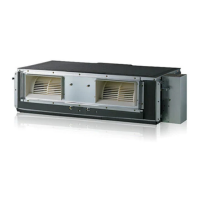
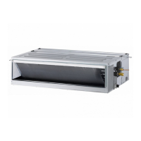
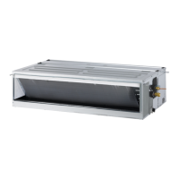
Introduces LG ducted indoor units for Multi V systems and refers to model lists.
Emphasizes personnel safety during installation and recommends reading the manual.
Specifies that installation is for trained personnel in construction, mechanical, and electrical disciplines.
States that personnel must follow applicable national, state, and local codes for installation.
Lists essential tools that the installer must provide for the installation process.
Lists necessary parts that the installer must provide for the installation process.
Explains the structure and meaning of model numbers for cassette indoor units.
Discusses R410A refrigerant properties, pressure, composition, and handling precautions.
Provides detailed specifications for High-Static M2 Chassis ducted indoor units.
Provides detailed specifications for High-Static M2 and M3 Chassis ducted indoor units.
Provides detailed specifications for High-Static B8 Chassis ducted indoor units.
Provides detailed specifications for Convertible Mid-Static MA Chassis ducted indoor units.
Provides detailed specifications for Mid-Static M1 Chassis ducted indoor units.
Provides detailed specifications for Mid-Static M2 Chassis ducted indoor units.
Provides detailed specifications for Mid-Static M3 Chassis ducted indoor units.
Provides detailed specifications for Low-Static Ducted L1/L2/L3 Chassis indoor units.
Provides detailed specifications for Vertical Air Handling Unit NJ Chassis.
Provides detailed specifications for Vertical Air Handling Unit NK Chassis.
Details electrical specifications for Mid and High-Static M1/M2/M3/B8 Chassis indoor units.
Details electrical specifications for Low-Static Ducted L1/L2/L3 Chassis indoor units.
Details electrical specifications for Vertical Air Handling Unit NJ/NK Chassis.
Provides dimensional drawings and measurements for the High-Static Ducted B8 Chassis indoor unit.
Provides dimensional drawings and measurements for the Mid and High-Static Ducted M2 Chassis indoor units.
Provides dimensional drawings and measurements for the Mid and High-Static Ducted M3 Chassis indoor units.
Provides dimensional drawings and measurements for the Mid-Static Ducted MA Chassis indoor unit.
Provides dimensional drawings and measurements for the Mid-Static Ducted M1 Chassis indoor unit.
Provides dimensional drawings and measurements for the Low-Static Ducted L1/L2/L3 Chassis indoor units.
Provides dimensional drawings and measurements for the Vertical Air Handling Unit NJ Chassis.
Provides dimensional drawings and measurements for the Vertical Air Handling Unit NK Chassis.
Illustrates refrigerant piping connections for various ducted indoor unit types.
Provides criteria for selecting an appropriate installation location for the indoor unit.
Offers guidance for installing units in areas exposed to unconditioned air.
Details the process of unpacking the unit and inspecting for any freight damage.
Provides general guidelines for mounting vertical and horizontal air handler units.
Offers specific instructions for installing air handler units in a horizontal-left configuration.
Covers duct connection procedures and requirements for vertical/horizontal air handler units.
Provides step-by-step instructions for installing the ducted indoor unit chassis.
Covers the initial steps for preparing the indoor unit's location and mounting.
Guides on the installation of wall-mounted zone controllers, including cable management.
Presents a table of indoor unit dimensions and weights for various chassis types.
Provides dimensions for connecting supply and return ducts to various indoor unit chassis.
Describes how to install Convertible Mid-Static Ducted MA Chassis units in a vertical orientation.
Details the procedure for installing the vertical conversion kit for specific indoor units.
Explains the wiring connections for the vertical installation conversion kit.
Guides on how to change the air inlet position from back to bottom for specific indoor units.
Explains the process of connecting refrigerant pipes, including dimensions and safety.
Outlines crucial preparation steps for refrigerant piping, including brazing and flare fitting creation.
Provides a step-by-step guide for creating proper flare fittings for refrigerant lines.
Details the correct procedure and torque for tightening flare nuts on refrigerant lines.
Covers best practices for handling, storing, and maintaining refrigerant piping materials.
Addresses refrigerant safety, concentration limits, and potential hazards like asphyxiation.
Describes the importance of proper brazing techniques and materials for system integrity.
Explains how to connect refrigerant pipes using flare fittings or brazing.
Provides guidelines for insulating refrigerant pipes to prevent moisture and maintain efficiency.
Explains the factory-mounted condensate pump and gravity drain options for indoor units.
Details condensate pipe connections for High, Mid, and Low Static Ducted units.
Covers drain line installation and trap requirements for specific ducted units.
Explains gravity condensate pipe connections for specific ducted indoor units.
Details condensate drainage for MA chassis units installed vertically.
Provides specific considerations for condensate drainage when installing MA chassis units vertically.
Offers drain information and installation guidance for Vertical/Horizontal Air Handler Units.
Guides the installation of condensation drain pipes for AHU units, including slope and material requirements.
Covers general wiring principles and the importance of separating power and communication cables.
Details best practices for making power and communication cable terminations.
Explains how to properly connect wires to terminal blocks, including screw tightening.
Outlines power supply requirements and specifications for indoor units, including grounding.
Details specifications for communication cables connecting outdoor, indoor, and heat recovery units.
Provides specifications for communication cables used between indoor units and remote controllers.
Explains wiring for group control configurations involving multiple indoor units.
Details how to connect communication cables to the indoor unit control box and terminal blocks.
Shows terminal block connections for communication cables in different indoor unit types.
Illustrates the location of power and communication terminals in Vertical/Horizontal Air Handler Units.
Provides instructions and safety precautions for connecting the power wiring to the indoor unit.
Continues power wiring instructions and covers communication cable connections.
Shows the wiring diagram for the High-Static Ducted B8 Chassis, including terminal functions.
Lists terminal functions and DIP switch settings for the B8 Unit.
Displays the wiring diagram for the Mid-Static and High-Static Ducted M2 Chassis.
Lists terminal functions and DIP switch settings for the M2 Unit.
Shows the wiring diagram for the Mid-Static and High-Static Ducted M3 Chassis.
Lists terminal functions and DIP switch settings for the M3 Unit.
Displays the wiring diagram for the Convertible Mid-Static Ducted MA Chassis.
Lists terminal functions and DIP switch settings for the MA Unit.
Shows the wiring diagram for the Mid-Static Ducted M1 Chassis.
Lists terminal functions and DIP switch settings for the M1 Unit.
Displays the wiring diagram for the Low-Static Ducted L1 Chassis.
Lists terminal functions and DIP switch settings for the L1 Unit.
Shows the wiring diagram for the Low-Static Ducted L2/L3 Chassis.
Lists terminal functions and DIP switch settings for the L2/L3 Units.
Displays the wiring diagram for the Vertical Air Handling Unit NJ Chassis.
Lists terminal functions and DIP switch settings for the NJ Frame.
Shows the wiring diagram for the Vertical Air Handling Unit NK Chassis.
Lists terminal functions and DIP switch settings for the NK Frame.
Details how to configure DIP switches for group control (main/sub) on indoor units.
Introduces typical control configurations for indoor units, including group control methods.
Explains LGRED technology for low-ambient heating operation in specific units.
Details compatibility of PRHR*3A heat recovery units with other LG VRF systems.
Outlines requirements for Gen 4 indoor units to operate with Gen 4 system features.
Guides on the proper installation location and procedure for wired remote controllers.
Provides instructions for installing wall-mounted sensors for optimal indoor unit operation.
Explains Group Control Method 1 using one wired remote controller as the main unit.
Describes Group Control Method 2 with two wired remote controllers (main and sub).
Explains Group Control Method 3 for grouping OAU and standard indoor units separately.
Details Group Control Method 4 using Simple Remote Controllers connected to one indoor unit.
Shows an example configuration for a remote control setup with various system components.
Checklist items for the initial rough-in phase of the indoor unit installation.
Checklist items related to ductwork installation and sealing.
Checklist items for proper refrigerant piping installation and safety.
Checklist items for installing the condensate system correctly.
Checklist items related to insulation for pipes and housing.
Checklist items for electrical connections, grounding, and conductor separation.
Checklist items for zone controller communication cable installation and configuration.
Checklist items for connecting the zone controller cable and setting DIP switches on the indoor unit control panel.
Provides a link to the full Limited Warranty terms and conditions.
Lists contact information for manufacturer representatives for various support needs.
| Category | Air Conditioner |
|---|---|
| Type | Multi V |
| Model | ARNU283M3A4 |
| Cooling Capacity | 28.0 kW |
| Heating Capacity | 31.5 kW |
| Refrigerant | R410A |
| Power Supply | 380-415V, 3Ph, 50Hz |