ENGLISH
Installation Manual 55
Test Run
■ Indoor unit error display
1. 1
st
and 2
nd
number represents indoor unit number.
Indoor unit number follows auto addressing number.
2. Last number represents sensor.
❈ Indoor unit number follows Auto addressing number.
■ Displaying outdoor unit error
1. 1
st
and 2
nd
number represents error content(code).
2. Last number represents outdoor unit number.
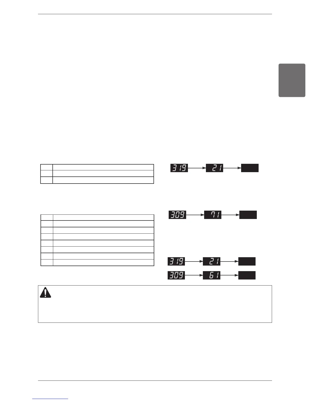
ex) Indoor unit No. 2 pipe inlet temperature sensor
error
ex) Outdoor unit liquid pipe temperature
sensor error
1 Outdoor Air Temperature
2 Heat Exchanger 1
4 Inverter Compressor Discharge Temperature
6 Suction Temperature
7 Liquid Pipe Temperature
9 SC pipe out
10 High Pressure Sensor
11 Low Pressure Sensor
ex) Indoor unit No.2 pipe inlet temperature sensor error and
outdoor unit suction temperature sensor error
1 Pipe inlet temperature sensor
2 Pipe outlet temperature sensor
3 Air temperature sensor
Error display during sensor inspection process is composed of 3 stages as shown below, and is proceeded by repeating
these stages
n Step 1 : Display of error existence : 309 or 319
- 309 : Inspect sensors of outdoor unit
- 319 : Inspect sensors of indoor unit
n Step 2: Display of error location
- In case of 309 (outdoor unit sensors)
2 digits on the left among 7 segments – Sensor Type (Table1)
1 digit on the right among 7 segments – Outdoor Unit Number
- In case of 319 (indoor unit sensors)
2 digits on the left among 7 segments – Indoor Unit Number
(Same as LGMV (automatic address configuration) indoor unit number)
1 Digit on the right among 7 segments – Sensor Type (Table 2)
n Step 3: Turn Off
h 1 error is displayed through 3 stages above and maximum of 5 errors are displayed.
Sensor Check Error Code Display
Displaying error content
CAUTION
1. Up to 5 number of errors is displayed continuously and repeatedly. In case 5 number of errors occurs, again perform
sensor checking after solving errors.
2. IDU in which error occurred operates air circulation mode.