SYSTEM ENGINEERING
| 73
HEAT PUMP CONDENSING UNIT ENGINEERING MANUAL
Due to our policy of continuous product innovation, some specifications may change without notification.
© LG Electronics U.S.A., Inc., Englewood Cliffs, NJ. All rights reserved. “LG” is a registered trademark of LG Corp.
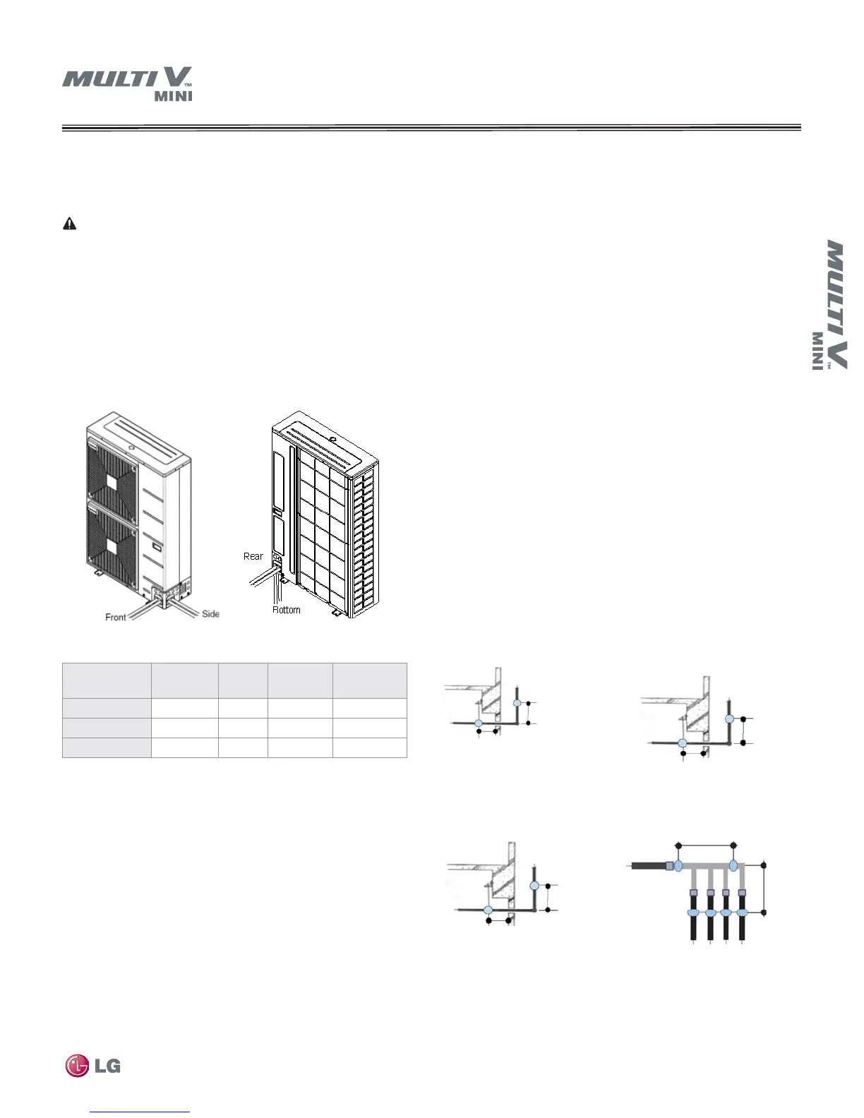
Refrigerant Pipe Connections
Note: When routing field-provided tubing inside the out-
door unit case, take care to avoid vibration damage to the
tubing. Mount the tubing so it does not make contact with
the compressor, unit casing, terminal cover, or mounting
bolts. Allow room for field installation.
Properly insulate fi eld-provided tubing inside the confi nes
of the unit casing.
Refer to Figure 44 for unit pipe connection options and
Table 27 for outdoor unit connection types.
Pipe Supports
A properly installed pipe system should be adequately supported to
avoid pipe sagging. Sagging pipes become oil traps that could lead
to equipment malfunction. Field-provided pipe supports should be
designed to meet local codes. If allowed by code, use fiber straps
or split-ring hangers suspended from the ceiling on all-thread rods.
Supports should never touch the pipe wall. Insulate the pipe first.
Place a second layer of insulation over the pipe insulation jacket to
prevent chafing and compression of the primary insulation within
the confines of the support pipe clamp. Pipe and insulation should
be allowed to move linearly as pipe temperature changes.
• Straight segments up to 3/4 inch OD should be supported at
least every 5 feet or per local codes if more stringent.
• Straight segments of 1 inch OD and larger copper pipe should
be supported every 6 feet or per local codes if more stringent.
• A properly installed pipe system will have sufficient supports
to keep pipes from sagging during the life of the system. As
necessary, place supports closer for segments where potential
sagging could occur.
Wherever the pipe changes direction, place a hanger within 12
inches on one side and within 12 to 19 inches of the bend on the
other side as shown in Figure 45. Support piping at indoor units
as shown in Figure 46. Support Y-Branch and Header fittings as
shown in Figure 47 and Figure 48.
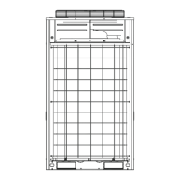
Figure 44: Outdoor Unit—Refrigerant Pipe Connections Options
Table 30: Outdoor Unit Refrigerant Pipe Connections
Model
Liquid Conn
(inches)
Type
Vapor Conn
(inches)
Type
ARUN036GS2
3/8 Braze 5/8 Braze
ARUN047GS2
3/8 Braze 5/8 Braze
ARUN053GS2
3/8 Braze 3/4 Braze
Figure 47: Pipe Support at
Y-Branch Fitting
PIPING DESIGN GUIDE
Figure 46: Pipe Sup-
port at Indoor Unit
Figure 45: Typical Pipe Sup-
port—Change in Pipe Direction
Figure 48: Pipe Support at
Header
~12"–19"
Max. 12"
Max. 12”
~ 12” – 19”
A
A+B ~ 12"–19"
B
Max. 12"
Max. 12"
Max. 12"
Max. 12"
Max.
Max. 12”
~ 12” – 19”
Max. 12”