84
|
CUT SHEET
Due to our policy of continuous product innovation, some specifications may change without notification.
© LG Electronics U.S.A., Inc., Englewood Cliffs, NJ. All rights reserved. “LG” is a registered trademark of LG Corp.
CUT-SHEET
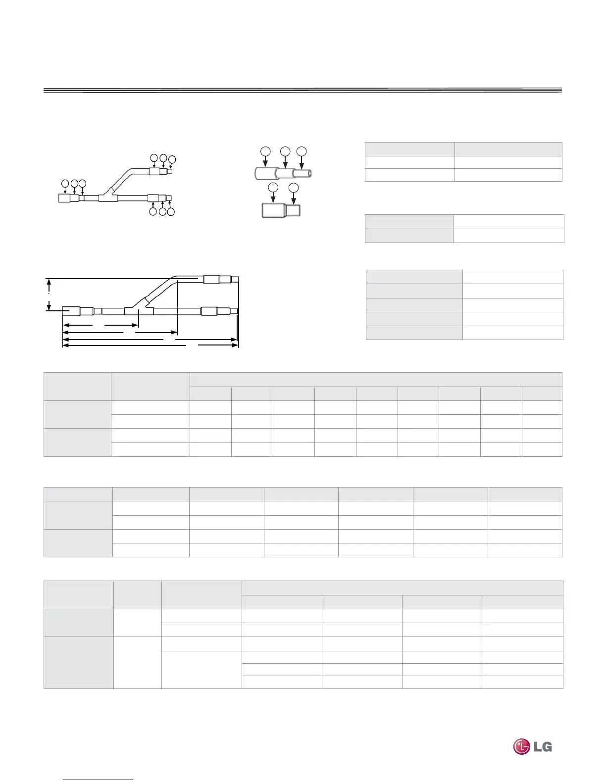
Table 39: Y-Branch Dimensions (in) (Reference Figure 74)
Model Y-Branch Type A B C D E
ARBLN01621
Liquid
2-29/32 6-9/16 8.0 11-1/16 11-1/2
Vapor
2-29/32 4-1/2 8.0 11-1/16 11-1/2
ARBLN03321
Liquid
2-29/32 4-1/2 8.0 12-5/8 13-1/16
Vapor
3-9/32 6-29/32 10-29/32 15-11/32 16-1/4
Table 40: Reducer Diameters (in) (Reference Figure 73)
Model Qty/Kit Reducer type
Port Identifi er
10 11 12 Length
ARBLN01621 2
Liquid
1/2 ID 3/8 OD — 2-3/4
Vapor
3/4 ID 5/8 OD — 2-3/4
ARBLN03321 3
Liquid
————
Vapor
1-1/8 ID 1 OD — 3-5/32
7/8 ID 3/4 OD — 2-3/4
1 ID 7/8 ID 3/4 OD 4-11/32
Y-Branch Kits
The Y-Branch kits include a Polyolefin foam,
clam shell, peel and stick, insulation jacket for
each Y-Branch.
LG Y-Branch fittings must be used. Field-sup-
plied branch fittings are not permitted.
Kit components must be kept free of debris and
dry before installation.
ID = Internal Diameter, OD = Outside Diameter
All dimensions in inches. Tolerance ± 0.25
inch.
Images are not to scale.
Must follow installation instructions in the ap-
plicable LG installation manual.
11
10
Figure 74: Y-Branch connection dimensions (Table 36)
Fitting Properties
Material
Copper
Design Pressure
551 psig
Insulation Jacket Properties
Material
Polyolefi n Foam
UL94 Flame Classifi cation
HF-1
Density
1.84 lbm/ft
3
Thermal Conductivity
.0208 Btuh/ft ºR
Thickness
0.5 Inches
Table 38: Y-Branch Connection Diameters (in-ID) (Reference Figure 72)
Model Y-Branch Type
Port Identifi er
123456789
ARBLN01621
Liquid
— 1/4 3/8 3/8 1/4 — 3/8 1/4 —
Vapor
— 5/8 1/2 1/2 5/8 — 1/2 5/8 —
ARBLN03321
Liquid
— 1/2 3/8 3/8 1/2 1/4 3/8 1/2 1/4
Vapor
1 7/8 3/4 5/8 3/4 1/2 5/8 3/4 1/2
E
B
Figure 73: Reducer parts (Table 37)
A
B
E
D
C
10 11 12
Nominal Capacity Range (Values expressed in BTUs)
Model Fitting Capacity
ARBLN1621 ≤ 54,600 connected capacity
ARBLN03321 ≤ 76,400 connected capacity
ID = Inside Diameter
Values expressed in BTUs
Figure XX - Y-branch and adapter connections
7
8
9
Outlet ports
5
6
4
1
2
3
Inlet ports
Outlet ports
Figure 72: Y-Branch connectors (Table 35)