Do you have a question about the LG MULTI V WATER 5 ARW Series and is the answer not in the manual?
| Refrigerant | R410A |
|---|---|
| Power Supply | 380-415V, 3Ph, 50Hz |
| Net Weight (Outdoor) | 285 kg |
| Energy Efficiency Ratio (EER) | 4.55 |
| Coefficient of Performance (COP) | 5.00 |
| Weight (Outdoor Unit) | 285 kg |
Defines the product family for the unit.
Specifies the operational type of the unit.
Lists the available capacity ratings for the units.
Details the electrical specifications for the units.
Describes the airflow direction options.
Indicates the system's efficiency rating.
Specifies the generation of the unit.
Lists available software formats and access methods.
Outlines the capabilities and functionalities of the LATS software.
Provides detailed mechanical specifications for the units.
Highlights key features and advantages of the product.
Presents general technical data and specifications.
Details the electrical specifications and ratings.
Outlines limitations for unit and indoor unit connections.
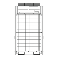
Provides physical dimensions of the units.
Shows electrical wiring schematics.
Illustrates refrigerant flow paths in different modes.
Presents sound pressure and power level data.
Details pressure drop characteristics in water circuits.
Lists available accessories for the units.
Overview of the WSU and its capabilities.
Specifies the operating temperature ranges for the units.
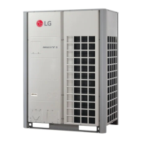
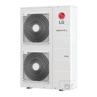
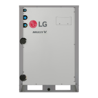
Describes the construction and features of the unit casing.
Details the components and refrigerant used in the system.
Explains the oil return system and technologies used.
Describes the type and features of the compressors.
Details the specifications of the heat exchanger.
Covers the electrical supply and protection aspects.
Outlines the control system components and communication.
Describes an optional kit for variable water flow control.
Overview of the product line's capabilities and advantages.
Requirements for using Generation 4 features.
Information on the unit's sound emission levels.
Explains how the system achieves optimal comfort.
Details the system's load matching capabilities.
Covers oil management and inverter technology.
Specifics on the oil management system.
Benefits of the inverter-driven compressor.
Highlights ease of installation and system integration.
Defines the operating capacity and temperature ranges.
Provides information on the unit's physical footprint.
Lists additional features like inverter compressors and certifications.
Technical data for single frame 208-230V units.
Technical data for single frame 460V units.
Technical data for higher capacity single frame 460V units.
Technical data for dual frame 208-230V units.
Technical data for dual frame 460V units.
Technical data for higher capacity dual frame 460V units.
Technical data for triple frame 208-230V units.
Technical data for higher capacity triple frame 208-230V units.
Electrical specifications for 208-230V models.
Electrical specifications for 460V models.
Guidelines for matching units and indoor units.
Dimensional drawings and details for single frame units.
Dimensional drawings and details for dual frame units.
Dimensional drawings and details for triple frame units.
Wiring diagrams for 208-230V models.
Wiring diagrams for 460V models.
Illustrates refrigerant flow for heat pump cooling.
Illustrates refrigerant flow for heat pump heating.
Illustrates refrigerant flow for heat recovery cooling.
Illustrates refrigerant flow for heat recovery heating.
Illustrates flow for simultaneous cooling operation.
Illustrates flow for simultaneous heating operation.
Illustrates flow for balanced simultaneous operation.
Illustrates flow for oil return operation.
Presents sound pressure and power data for models.
Sound pressure graphs for 208-230V models.
More sound pressure graphs for 208-230V models.
Additional sound pressure graphs for 208-230V models.
Further sound pressure graphs for 208-230V models.
Final sound pressure graphs for 208-230V models.
Sound pressure graphs for larger 208-230V models.
Sound pressure graphs for 460V models.
More sound pressure graphs for 460V models.
Additional sound pressure graphs for 460V models.
Further sound pressure graphs for 460V models.
Sound pressure graphs for larger 460V models.
More sound pressure graphs for 460V models.
Further sound pressure graphs for 460V models.
Final sound pressure graphs for 460V models.
Details on Y-branches for indoor units.
Y-branches for indoor units in heat recovery systems.
Details on Y-branches for outdoor units.
Y-branches for outdoor units in heat pump systems.
Y-branches for outdoor units in heat recovery systems.
Information on refrigerant pipe headers.
Details on header kits and their properties.
Software for system monitoring and diagnostics.
Wiring and connection details for heat pump operation.
Wiring and connection details for heat recovery operation.
Settings for DIP switches for Gen 4 compatibility.
Limitations for heat pump system piping.
Limitations for heat recovery system piping.
Piping rules for separated water source units.
Guidelines for unit placement.
Instructions for safely moving and lifting units.
Guidelines for installing the units.
Information on unit corner weights for placement.
Guidelines for taking measurements for piping.
Details on maximum allowable pipe lengths.
Requirements for refrigerant traps.
Guidelines for allowable pipe slope.
Criteria for selecting the optimal installation location.
List of unsuitable installation locations and practices.
Specifics on transporting and lifting the units.
Installation guidelines for single frame units.
Installation guidelines for dual frame units.
Installation guidelines for triple frame units.
Details on anchor bolt placement for installation.