62 | ELECTRICAL CONNECTIONS
MULTI V Water 5 Water Source Unit Engineering Manual
Due to our policy of continuous product innovation, some specications may change without notication.
© LG Electronics U.S.A., Inc., Englewood Cliffs, NJ. All rights reserved. “LG ” is a registered trademark of LG Corp.
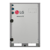
Figure 8: Example of a Typical Heat Pump Operation Power Wiring and Communications Cable Schematic.
SYSTEM FOR HEAT PUMP
OPERATION, 208-230V AND 460V
• Ground wiring is required to prevent accidental electrical shock during current leakage, communication problems from electrical noise, and
motor current leakage. Do not connect the ground line to the pipes. There is risk of re, electric shock, explosion, physical injury or death.
• Install a main shutoff switch that interrupts all power sources simultaneously. There is risk of fire, electric shock, explosion, physical injury
or death.
• Communication cable between Main ODU to Sub ODU(s), and Main ODU to IDUs to be 18 AWG, 2-conductor, twisted, stranded, shielded.
Ensure the communication cable shield is properly grounded to the Main ODU chassis only. Do not ground the ODU to IDUs
communication cable at any other point. Wiring must comply with all applicable local and national codes. Inadequate connections may
generate heat, cause a fire, and physical injury or death.
• The GND terminal at the main PCB is a negative terminal for dry contact, not a ground. Inadequate connections may generate heat, cause
a fire, and physical injury or death.
• Make sure that the terminal numbers of main water source unit and sub water source unit(s) match (A to A, B to B). The system will
malfunction if not properly wired.
• Maintain polarity throughout the communication network. The system will malfunction if not properly wired.
• If the system operates in reversed phase, it may break the compressors and other components.
• If there is a possibility of reversed phase, phase loss, momentary blackout, or the power goes on and off while the system is operating, install
a eld-supplied phase loss protection circuit. Operating the system in reverse phase may break the compressor and other unit components.
Main WSU
Indoor Units
Main Switch
Sub WSU Sub WSU
Pull Box
(Installer option)
R
(L1)
Switch
Switch
Switch
Fused
Disconnect
S
(L2)
T
(L3)
R
(L1)
S
(L2)
T
(L3)
R
(L1)
S
(L2)
T
(L3)
Power Supply
3 Phase, 60Hz
208/230V
or 460V
Power Supply
1 Phase, 60Hz
208/230V
Pull Box
(Installer
option)
Pull Box
(Installer
option)
Pull Box
(Installer
option)
Power Cable:
Communication Cable:
Fused
Disconnect
Fused
Disconnect
L1
L2
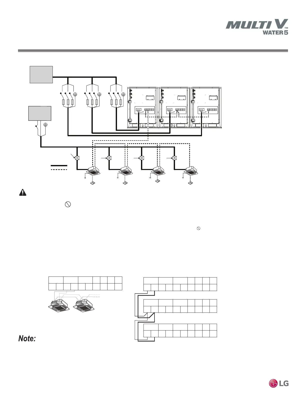
Figure 9: Close-up of Heat Pump Operation Communications Cable Schematic.
Heat Pump Operation
Communications Cable Between Main Outdoor Unit and Indoor Unit
B
ODU ID U CENTRAL DRY1 DRY2 GND 12 V
A B
A
B A
Main
Outdoor Unit Communication Terminal Block
B
ODU IDU CENTRAL DRY1 DRY2 GND 12 V
A B
A
B A
B
DRY1 DRY2 GND 12 V
A B
A
B A
B
DRY1 DRY2 GND 12 V
A B A
4(B)
3(A)
4(B)
3(A)
B
A
Communications Cable Between Main Outdoor Unit and Sub Outdoor Unit(s)
Main
Outdoor Unit Communication Terminal Block
Sub 1
Outdoor Unit Communication Terminal Block
Sub 2
Outdoor Unit Communication Terminal Block
Indoor Unit Indoor Unit
ODU IDU CENTRAL
ODU IDU CENTRAL
 Loading...