LIMITS / PLACEMENT | 73
Piping Limitations and Placement Considerations
Due to our policy of continuous product innovation, some specications may change without notication.
© LG Electronics U.S.A., Inc., Englewood Cliffs, NJ. All rights reserved. “LG ” is a registered trademark of LG Corp.
WSU: Water Source Unit
HRU: Heat Recovery Unit
IDU: Indoor Unit
A: Main Pipe from Water Source Unit
to First Y-branch.
B: HRU to HRU, Y-branch to HRU, HRU
to Header, or Y-branch to Y-branch.
C: Heat Recovery Unit / Header to
Indoor Unit.
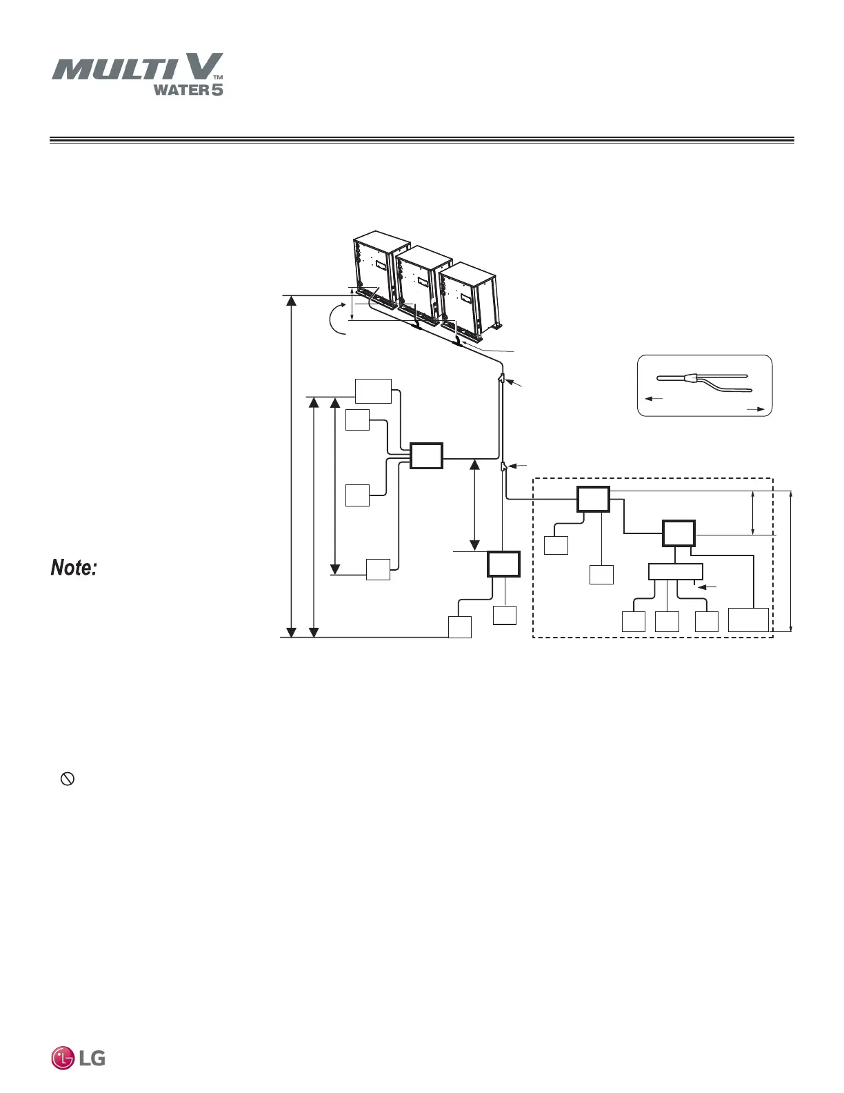
Example of Pipe Sizing When Installing a Heat Recovery System
Example: Triple-frame system,
four (4) heat recovery units, one
(1) header, and twelve (12) indoor
units connected
• Always reference the LATS Multi V
software report.
• The largest capacity WSU must be the
main unit in a multi-frame system.
• Main WSU capacity must be greater
than or equal to the sub1 WSU
capacity, and, where applicable, sub1
WSU capacity must be greater than or
equal to the sub2 WSU capacity.
• Connection piping from branch to branch cannot exceed the main pipe diameter (A) used by the water source unit.
• Install the header branches or heat recovery units so that the pipe distances between the between the connected indoor units are mini-
mized. Large differences in pipe distances can cause indoor unit performances to fluctuate.
• Y-branches and other header branches cannot be installed downstream of the initial header branch.
• Total capacity of indoor units in series connection of heat recovery units ≤192,400 Btu/h.
• If large capacity indoor units (>12,000 Btu/h with piping sizes >5/8Ø / 3/8Ø) are installed, the valve group setting must be used. (Refer to
the PCB of the heat recovery unit for the valve group control setting.)
PIPING LIMITATIONS
For Systems Designed for Heat Recovery Operation
Following pages present Multi V Water 5 piping limitations and are for illustrative purposes only. Designers MUST use LATS when designing LG VRF
systems.
Figure 17: Heat Recovery Triple-Frame Connections.
Elevation 1 ≤164 ft.
Elevation 2 ≤131 ft.
Sub 1 WSU
Sub 2 WSU
A
Y-branch (first)
B
C
Closest
IDU
C
HRU
C
C
B
B
C
C
C
C
B
B
C
C
x
Header
C C
Elevation 5
≤16 ft.
B
Y-branch (second)
HRU
HRU
HRU
IDU
IDU
IDU
IDU
IDU
IDU
IDU
IDU IDU IDU
Farthest
IDU
Brazed
cap
98 ft.*
16 ft.
Main WSU
Elevation 3 ≤49 ft.
Multi-Frame
Connector
To indoor units
To WSU
Y-branch
Elevation 4 49 ft.
* Up to 131 ft. may be possible with certain applications. Contact LG Engineering for additional
information.
 Loading...