Do you have a question about the LG MULTI V ARUN072BTE4 and is the answer not in the manual?
Safety warnings and cautions for unit installation, covering fire, electrical shock, and physical injury risks.
Safety precautions related to electrical wiring, including high voltage, grounding, and connections, to prevent injury or death.
Safety guidelines for operating the unit, covering electrical hazards, environmental factors, and proper procedures to avoid damage.
Explains the coding system for identifying LG Multi V Outdoor Units (ODU) based on family, type, capacity, ratings, etc.
Details the nomenclature for LG Multi V Heat Recovery Units (HRU), including family, ports, and series number.
Describes normal operation functions for compressor, fan, and EEVs in cooling and heating modes.
Explains how fuzzy logic is used for stable compressor performance by maintaining evaporating and condensing temperatures.
Details the control logic for Main EEV, Subcooling EEV, and Vapor Injection for master-slave outdoor units.
Explains the oil return operation to recover and return oil to the compressor in cooling and heating modes.
Details the component operations during defrost control to eliminate ice and restore heat exchanger performance.
Describes partial defrost operation that defroths parts of the heat exchanger separately for continuous heating mode.
Outlines stop operation control for cooling and heating modes, and the oil equalizing control for compressors.
Details high and low pressure protection controls for compressor and fan in cooling and heating modes.
Explains discharge temperature control actions for compressor and EEVs based on temperature ranges.
Outlines inverter protection control based on AC input and compressor current limits in cooling and heating modes.
Describes phase detection errors and their corresponding error numbers for three-phase power systems.
Mentions the pressure sensor switch on the Main PCB and its function.
Guides through the four initial setup steps, including factory settings, communication checks, and PCB error checks.
Details the process of indoor unit auto addressing using the red address button and the Main PCB LED display.
Explains how to select modes, functions, options, and values using buttons and DIP switches for system configuration.
Describes automatic and manual emergency operation procedures for inverter compressor failures.
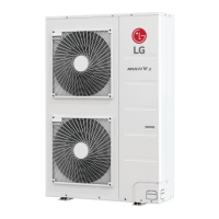
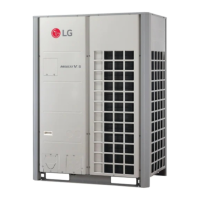
The LG Multi V IV is a series of variable refrigerant flow (VRF) outdoor units designed for both heat pump and heat recovery applications, offering a range of capacities from 6.0 to 42.0 tons. These units are engineered to provide efficient comfort cooling and heating for various commercial and residential settings.
The Multi V IV system operates on a sophisticated control logic to ensure stable and efficient performance. At its core, the system utilizes fuzzy logic for compressor control, maintaining optimal evaporating temperatures (Te) during cooling and condensing temperatures (Tc) during heating. This intelligent control adjusts compressor operation based on the cooling and heating load, ensuring that the system operates at its most efficient point.
The outdoor units are available in two main types: Heat Pump (ARUN series) and Heat Recovery (ARUB series). Heat pump units provide either cooling or heating to all connected indoor units simultaneously. Heat recovery units, on the other hand, offer the flexibility of simultaneous cooling and heating to different indoor units, making them ideal for buildings with diverse thermal demands.
Key components like the Main Electronic Expansion Valve (EEV) and Subcooling EEV are precisely controlled. The Main EEV uses fuzzy logic to maintain a stable degree of superheat at the evaporator outlet during heating, while the Subcooling EEV maintains a stable degree of subcool at the subcooler outlet during cooling. This precise control of refrigerant flow is crucial for maximizing efficiency and preventing issues like liquid floodback to the compressor.
The system incorporates advanced protection controls to safeguard its components and ensure reliable operation. These include pressure protection controls for both high and low pressures in cooling and heating modes, discharge temperature control to prevent compressor overheating, and inverter protection control to manage current draw and prevent damage to the inverter compressor.
The Multi V IV system offers several features designed to enhance user experience and system flexibility:
The Multi V IV is designed with maintenance in mind, incorporating features that facilitate diagnostics and servicing:
The LG Multi V IV system is a robust and intelligent solution for climate control, offering advanced operational features and comprehensive maintenance tools to ensure reliable and efficient performance over its lifespan.
| Model | ARUN072BTE4 |
|---|---|
| Category | Heat Pump |
| Brand | LG |
| Series | MULTI V |
| Power Supply | 208-230V/60Hz/1Ph |
| Refrigerant | R410A |
| Liquid Pipe (in) | 3/8 |
| Power Supply (V/Hz/Ph) | 208-230/60/1 |
| Capacity Control | Inverter |
| Refrigerant Control | Electronic Expansion Valve |
| Cooling Operating Range (°F DB) | 23 ~ 115 |
| Compressor Type | Scroll |
| Compressor (Oil Type) | POE |
| Fan Motor Type | DC |