Do you have a question about the LG OK75 and is the answer not in the manual?
Notes for transport, storage, and repair of the pick-up module.
Essential preparations and notes for performing repairs on compact disc players.
Information on handling sensitive electronic components to prevent static damage.
Details on hidden key modes, entrance, and exit keys for system operation.
Guide for downloading audio program firmware via USB.
Guide for downloading CD program firmware via USB.
Guide for downloading EQ & Demo program firmware via USB.
Steps for updating device firmware wirelessly via Bluetooth App.
Detailed steps for firmware download, transfer, and flashing.
Technical specifications for system components and performance.
Step-by-step instructions for removing the left and right side panels.
Initial steps for disassembling the top panel of the unit.
Further steps for removing the top panel, including screw removal.
Instructions for removing the rear panel and initial main set disassembly.
Steps for disconnecting cables and the power cord from the main set.
Final steps for grasping and removing the main set assembly.
Visual identification of components in the cabinet and main frame section.
Visual breakdown of the deck mechanism components.
Identification of packing accessories like antenna, ferrite core, and remote.
Troubleshooting power issues related to fuses, thermistors, and bridge diodes.
Troubleshooting power issues related to fuses and FETs in the SMPS.
Troubleshooting booting problems related to IC501 on the main board.
Troubleshooting VFD display issues by checking the VFD component.
Troubleshooting booting problems related to specific voltage rails.
Troubleshooting booting issues related to the X500 crystal.
Troubleshooting booting issues related to the serial flash IC503.
Troubleshooting MD operation by checking the spindle motor.
Troubleshooting MD operation by checking the sled motor.
Troubleshooting MD operation by checking the tray open/close motor.
Troubleshooting MD operation by checking the laser tracking actuator.
Troubleshooting MD operation by checking the laser focusing actuator.
Troubleshooting no sound issues related to the digital audio amplifier.
Troubleshooting no sound issues when playing CDs.
Troubleshooting no sound issues when using USB playback.
Troubleshooting no sound issues with the AUX input.
Troubleshooting no sound issues with the tuner function.
Troubleshooting no sound issues with the portable input.
Troubleshooting no sound issues with the microphone input.
Troubleshooting no sound issues with Bluetooth playback.
Troubleshooting no sound issues with the optical input.
Flowchart for troubleshooting SMPS power supply issues.
Flowchart for troubleshooting issues when no PVDD is detected.
Flowcharts for troubleshooting LED and VFD display problems.
Flowchart for checking and troubleshooting the MCS part.
Flowchart for checking and troubleshooting the FLD display.
Flowchart for checking and troubleshooting PWM modulation signals.
Flowchart for checking and troubleshooting the power amplifier.
Flowchart for checking Tuner and AUX input functions.
Flowchart for checking the tuner function and operation.
Flowchart for troubleshooting CD playback issues.
Flowchart for troubleshooting USB playback and file recognition.
Display of signal waveforms for DSP IC501, including crystal signals.
Waveforms and pinout diagram for SDRAM IC502.
Waveforms and circuit diagram for the Servo IC401.
Waveforms and pinout for the Motor Driver IC400.
Waveforms for ADC IC301 (I2S) and USB data signals at CN502.
Waveforms for Bluetooth TX/RX/RST signals at CN504.
Diagram showing wiring and connections between major modules and boards.
Overview of the system's functional blocks and their interconnections.
Table listing expected IC voltages and SMPS capacitor/diode details.
Tables listing main capacitor values and connector voltage specifications.
Voltage readings for specific connectors: CN201, CN504, CN106, CN107.
Voltage readings for additional connectors: CN701, CN102, CN104, CN103, CN462, CNS103, CNF103, CNF104.
Top view diagram of the SMPS printed circuit board.
Bottom view diagram of the SMPS printed circuit board.
Top view diagram of the main printed circuit board.
Bottom view diagram of the main printed circuit board.
Top view diagram of the top printed circuit board.
Bottom view diagram of the top printed circuit board.
Top view diagram of the Jack & RMC printed circuit board.
Top view diagrams for Sparkle LED UP and DOWN boards.
Top view diagrams for X-Flash LED and Speaker LED boards.
Steps to remove the cover top and clamp assembly of the deck mechanism.
Instructions for removing the tray disc from the deck mechanism.
Steps for removing the pick-up assembly and base up/down mechanism.
Steps for removing belts, gears, motor assembly, and FFC cable.
Exploded view detailing components of the deck mechanism DM19D.
| Output Power | 1000W |
|---|---|
| Bluetooth | Yes |
| Karaoke Creator | Yes |
| DJ Effects | Yes |
| USB Playback | Yes |
| Multi Jukebox | Yes |
| Party Accelerator | Yes |
| Type | Mini Hi-Fi System |
| Audio Playback | MP3, WMA |
| FM Radio | Yes |
| CD Player | Yes |
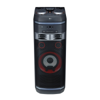
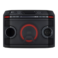
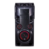
| Brand | LG |
| Model | OK75 |
| Category | Stereo System |
| Disc Formats | CD, CD-R, CD-RW |
| Radio | FM |
| Audio Inputs | USB |
| Speaker Configuration | 2.0 Channel |