COMMUNICATION KIT INSTALLATION
15
ENGLISH
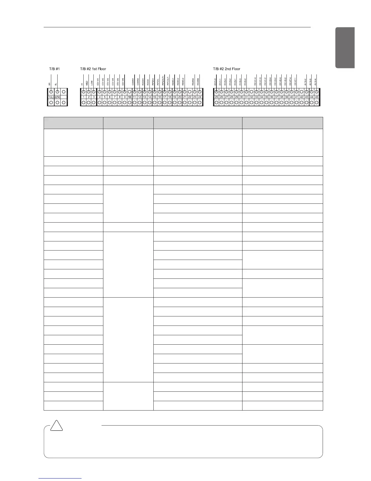
Terminal Block No. Connection Function Remark.
1(L) / 2(N) Power Supply
220-240 V~ 50 Hz
220 V~ 60 Hz
208/230 V~ 60 Hz
1-3 To AHU Fan Signal High/Mid/Low
4-9 To EEV Kit EEV Kit -
11-12 To AHU Communication Line Internet A, B
13-14
To Indoor Unit
Room Thermistor -
15-16 Pipe In Thermistor -
17-18 Pipe Out Thermistor -
19-21 Remote Controller -
23-24 To Outdoor Unit RS485 Communication -
25
Digital Input
DI 01-3 Operation ON/OFF
26 DI 01-1 Common Line
27 DI 23-3
Mode Change
28 DI 23-2
29 DI 23-1 Common Line
30 DI 45-3
Air Flow Rate
31 DI 45-2
33
Digital Output
DO 01-4 Running Status (ON/OFF)
34 DO 01-3 Common Line
35 DO 01-2 Comp. Status (ON/OFF)
36 DO 23-4
Running Mode
37 DO 23-2
38 DO 45-4
Air Flow Rate
39 DO 45-2
40 DO 67-4 Error Status
41 DO 67-1 Common Line
43
Analog Input
AI 10-2 Capacity Control
44 AI 10-3 Common Line
45 AI 10-4 Room Temperature Setting
CAUTION
If you want to use Analogue Input signal for a variable capacity and a set temperature of
room, you have to connect the wiring of AI 10-2, AI 10-3, AI 10-4.
!
Electric Wiring Work