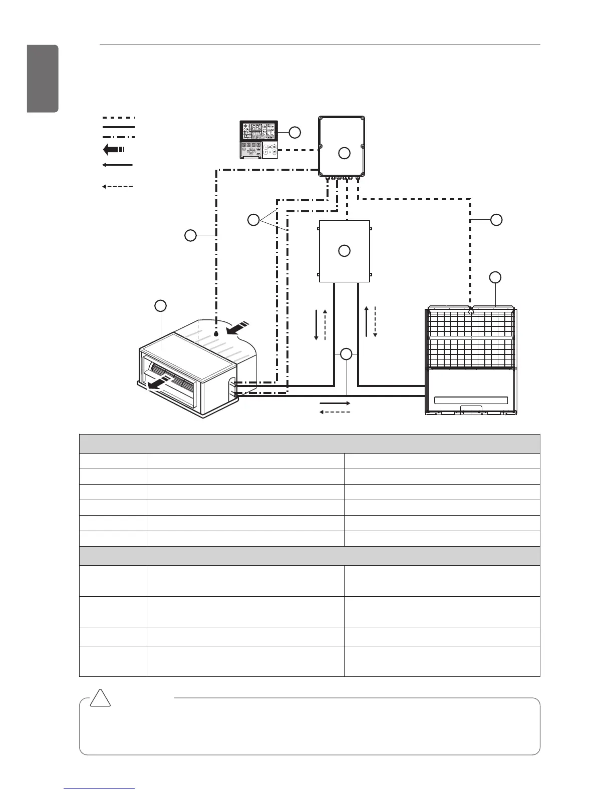
Parts and components
No. Name Remarks
1 Air Handling Unit Field supply
2 Outdoor Unit Multi V
3 AHU Communication Kit(PRDCA0) -
4 AHU EEV Kit(PRLK048A0/PRLK096A0) -
5 Field piping Field supply
Wiring connections
6 Communication Kit Wiring
Power supply and communication
between comm. kit and outdoor unit
7
Pipe thermistors
(EBG61287703/EBG61287704)
Evaporator (In/Out) control of Air Han-
dling Unit
8 Room thermistor (EBG61106821) Return air control
9
Remote controller(PQRCVSL0
/ PQRCVSL0QW)
Optional accessory
CAUTION
For Installation of Room thermistor (No. 8), always place it at the inlet of Heat Exchanger.
Otherwise, it might not operate properly.
!
INSTALLATION SCENE