Do you have a question about the LG RF-20CA80VE and is the answer not in the manual?
General recommendations for safe servicing practices.
Details sources and precautions related to X-ray radiation.
Explains procedures for AC leakage current checks for safety.
Outlines essential precautions for all servicing operations.
Discusses handling components sensitive to static electricity.
Provides recommended techniques for soldering components.
Details procedures for removing and replacing various components.
Provides instructions for repairing damaged circuit board traces.
Details video input systems and intermediate frequencies.
Lists tuning ranges, systems, and antenna input impedance.
Describes sound output, voice coil impedance, and external connections.
Lists additional features like auto program and teletext.
Explains the functions of buttons on the remote control handset.
Instructions for installing batteries in the remote control.
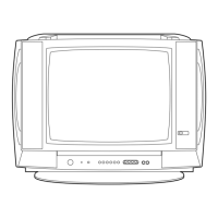
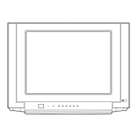
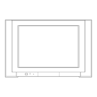
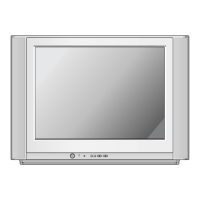
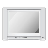
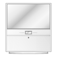
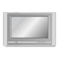
Details the functions of buttons and indicators on the TV's front panel.
Steps for removing the chassis and back/front cabinets.
Procedures for safely removing the picture tube assembly.
Essential safety warnings for handling the picture tube.
Safety precautions and required test equipment for adjustments.
Steps for adjusting CDL data using SVC-0 mode.
Guides for adjusting OPTION-1 and OPTION-2 settings.
Procedures for adjusting picture focus using FBT volume.
Steps for adjusting screen voltage using FBT volume.
How to adjust white balance using color analyzer.
Steps for adjusting AGC voltage using remote controller.
Steps before performing deflection data adjustments.
Provides initial default values for deflection settings.
Details adjustments for Vertical Linearity, Amplitude, Shift, and S-Correction.
Steps to adjust picture purity using magnets and yoke.
Detailed steps to align color convergence using yoke and magnets.
Illustrates the overall system architecture and component connections.
Visual representation of TV components and their assembly.
Lists components with part numbers and descriptions based on the exploded view.
Visual representation of CB90 model components and assembly.
Lists components for CB90 model with part numbers.
Lists replacement ICs and diodes with part numbers.
Lists replacement capacitors with part numbers.
Lists replacement resistors with part numbers.
Lists replacement fuses, coils, and transformers.
Lists replacement switches and filter/crystal components.
Lists accessories, sockets, thermistors, tuners, and other miscellaneous parts.
Detailed circuit schematic for the MC-019A chassis.
Diagram showing the physical layout of components on the printed circuit board.
Guide for identifying component locations on the PCB.
Contains specific service sheet information for the model.