EasyManua.ls Logo

LG RF-21FA20 - User Manual

LG RF-21FA20
30 pages
Print Icon
To Next Page IconTo Next Page
Loading...
COLOR TV
SERVICE MANUAL
CAUTION
BEFORE SERVICING THE CHASSIS,
READ THE SAFETY PRECAUTIONS IN THIS MANUAL.
CHASSIS : MC-014A
MODEL:RF-21FA20/Q/PQ
MODEL:CF-21Q20EH
website:http://biz.LGservice.com
e-mail:http://www.LGEservice.com/techsup.html
All manuals and user guides at all-guides.com
Question and Answer IconNeed help?

Do you have a question about the LG RF-21FA20 and is the answer not in the manual?

Summary

SAFETY PRECAUTIONS

Important Safety Notice

Key safety-related characteristics and replacement guidelines.

General Guidance for Servicing

Guidelines for safe servicing, handling components and picture tubes.

X-RAY Radiation Warning

Explains X-RAY radiation source and protection measures.

AC Leakage Current Checks

Procedures for checking AC leakage current for safety.

SPECIFICATIONS

Video, IF, and Tuning Specifications

Covers video input systems, IF, tuning ranges, and systems.

Audio, Features, and Display Specs

Details sound output, OSD, voice coil impedance, and features.

External Connectivity and I;O

Describes external connections and input/output signal levels.

DESCRIPTION OF CONTROLS (Remote Handset)

Remote Control Functions (Part 1)

Details POWER, MUTE, ARC, TV/AV, EYE, TURBO buttons.

Remote Control Navigation and Selection

Explains program/menu selection, volume, and OK button.

Remote Control Memory and VCR Functions

Covers Status Memory and VCR buttons.

REMOTE CONTROL DETAILS

Remote Control Functions (Part 2)

Details I/II, LIST, PIP, MENU, SWAP, SLEEP, and colored buttons.

Remote Control Battery Installation

Instructions for installing batteries in the remote control handset.

Front Panel Controls

Front Panel Power and Indicators

Describes the main power switch and standby indicator light.

Front Panel Buttons and Sockets

Explains functions of front panel buttons and external sockets.

Eye Function Control

Explains the 'Eye' function for picture adjustment.

DISASSEMBLY INSTRUCTIONS

Important Service Precautions

Notes on using isolation transformers and handling components.

Cabinet and Speaker Removal

Steps for removing the back cabinet and speakers.

CPT and Picture Tube Handling Caution

Procedures for CPT removal and safe handling of the picture tube.

ADJUSTMENT INSTRUCTIONS

Safety and Equipment for Adjustments

Safety guidelines and required test equipment for adjustments.

RF AGC and Screen Voltage Adjustments

Procedures for RF AGC and screen voltage adjustments.

Focus and Deflection Data Adjustments

Steps for focus adjustment and deflection data setup.

ADJUSTMENT PROCEDURES (Continued)

Horizontal Geometry Adjustments

Adjustments for EW, EP, EC, ET parameters.

Initial Adjustment Data Lists

Reference data for various adjustment parameters.

White Balance Adjustment Procedure

Steps for adjusting white balance for color accuracy.

OPTION Adjustment

Option 1 and Option 2 Functions

Settings for OPTION 1 (YUV/W, GAME, etc.) and OPTION 2 (SCART, AV2, etc.).

Option 3 Functions

Settings for OPTION 3 (200PR, CH+AU, etc.).

Trouble Shooting (No Power & Vertical Deflection)

No Power Issues (SMPS)

Troubleshooting flowchart for no power when SMPS is working or not.

No Vertical Deflection Troubleshooting

Troubleshooting steps for issues with vertical deflection.

Trouble Shooting (Screen & Distortion)

Heater, Screen, and Waveform Issues

Troubleshooting for heater element, screen, and waveform anomalies.

Barrel Distortion Troubleshooting

Steps for diagnosing and fixing barrel distortion.

Trouble Shooting (Sound Issues)

No Sound Troubleshooting (Picture OK)

Flowchart for troubleshooting sound issues when picture is normal.

Headphone Jack Sound Issues

Troubleshooting for sound problems specific to the headphone jack.

Trouble Shooting (Channel & PIP)

Channel Reception Troubleshooting

Troubleshooting flowchart for problems catching channels.

No PIP Troubleshooting

Steps for diagnosing issues with the PIP feature.

EXPLODED VIEW: 21 FA20

Exploded Diagram (21 FA20)

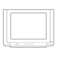
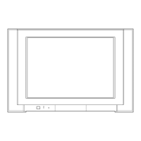
Visual representation of parts assembly for the 21FA20 model.

EXPLODED VIEW PARTS LIST (21 FA20)

Parts Identification by Location (21 FA20)

List of parts with location numbers, part numbers, and descriptions.

EXPLODED VIEW: 21 Q20

Exploded Diagram (21 Q20)

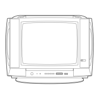
Visual representation of parts assembly for the 21Q20 model.

EXPLODED VIEW PARTS LIST (21 Q20)

Parts List by Location (21 Q20)

Detailed list of parts for the 21Q20 model with location and part numbers.

REPLACEMENT PARTS LIST (Semiconductors)

IC Components List

List of replacement IC parts with part numbers and descriptions.

Diode Components List

List of replacement diode parts with part numbers and descriptions.

Transistor Components List

List of replacement transistor parts with part numbers and descriptions.

REPLACEMENT PARTS LIST (Capacitors Part 1)

Capacitor Components (Page 21)

List of replacement capacitor parts with part numbers and descriptions.

REPLACEMENT PARTS LIST (Capacitors Part 2 & Connectors)

Capacitor Components (Page 22)

List of replacement capacitor parts with part numbers and descriptions.

Connector Components List

List of replacement connector parts with part numbers and descriptions.

REPLACEMENT PARTS LIST (Other Components)

Transistor Components (Continued)

List of replacement transistor parts with part numbers and descriptions.

Core, Coil, and Fuse Components

List of replacement core, coil, and fuse parts.

Resistor Components (Part 1)

List of replacement resistor parts with part numbers and descriptions.

REPLACEMENT PARTS LIST (Resistors Part 2)

Resistor Components (Page 24)

List of replacement resistor parts with part numbers and descriptions.

REPLACEMENT PARTS LIST (Resistors Part 3)

Resistor Components (Page 25)

List of replacement resistor parts with part numbers and descriptions.

REPLACEMENT PARTS LIST (Miscellaneous)

Resistor Components (Part 4)

List of replacement resistor parts with part numbers and descriptions.

Spark Gap, Switch, Filter & Crystal

Lists spark gaps, switches, and filters.

Accessories List

Lists accessories like manuals and remote controllers.

SCHEMATIC DIAGRAM

MC-014 A Chassis Schematic

Detailed schematic diagram of the MC-014A chassis.

PRINTED CIRCUIT BOARD & BLOCK DIAGRAM

Printed Circuit Board Layout

Shows the layout of components on the main PCB.

Block Diagram Overview

High-level functional block diagram of the TV system.

SVC. SHEET

Service Sheet Data

Contains specific service data for the model.

Overview

This document is a service manual for the LG Color TV models RF-21FA20/Q/PQ and CF-21Q20EH, chassis MC-014A. It provides comprehensive information for servicing, including safety precautions, specifications, control descriptions, disassembly instructions, adjustment procedures, and troubleshooting.

Function Description

The LG Color TV is a television receiver designed for displaying video and audio content. It supports multiple video input systems and tuning ranges, offering various features for enhanced viewing and listening experiences. The television can be controlled via a remote control handset or buttons on the front panel.

Important Technical Specifications

Video Input System:

  • PAL-B/G, D/K, I/I
  • SECAM-B/G, D/K
  • NTSC 4.43 (AV)

Intermediate Frequency (Unit: MHz):

  • VISION IF: 38.9MHz
  • COLOR IF:
    • 34.47MHz (4.43)
    • 35.32MHz (3.58) (NTSC-M)
    • VIF-4.25000MHz (SECAM)
    • VIF-4.40625MHz
  • SOUND IF:
    • 33.4MHz (B/G)
    • 32.9MHz (I/I)
    • 32.4MHz (D/K)

Power Requirements:

  • Power requirement: 110~240V, 50/60Hz
  • Power consumption: 95W

CPT (Cathode Ray Tube):

  • True Flat CPT (Flatron)

Tuning Range:

  • For TV:
    • VHF-Low: B/G Ch2-4, D/K Ch1-5, I/I S1'-S3', S1
    • VHF-High: B/G Ch5-12, D/K Ch6-12, I/I Ch4-13, S2-S10, S11-S20
    • Hyper: S21-S41
    • UHF: Ch21-69
  • For CATV: All ranges are supported.

Tuning System:

  • FVS (Frequency Synthesized Tuning System)
  • 100 Programme memory

Antenna Input Impedance:

  • VHF/UHF 75 ohm, unbalanced

OSD (On Screen Display):

  • WINDOW 3D Type

Voice Coil Impedance:

  • 8 ohm

Sound Output:

  • 10W+10W (Max 12W+12W)
  • Dual/Stereo: AV Stereo

External Connection:

  • Head Phone Jack (Front or Side)
  • A/V in: 1 pair (Front or Side)
  • A/V in/out (Back)

External In/Output:

  • Audio-In: 0.5Vrms ± 3db, over 10Kohm
  • Audio-Out: 0.5Vrms ± 3db, below 1Kohm
  • Video-In/Out: 1Vp-p ± 3db, 75ohm

Usage Features

The LG Color TV offers a variety of user-friendly features:

  • Remote Control Handset: Provides full control over all TV functions, including power, mute, volume, channel selection, menu navigation, and special features.
  • Front Panel Controls: Essential functions like power, volume, channel, and menu access are available directly on the TV's front panel.
  • Picture and Sound Adjustments:
    • ARC (Aspect Ratio Control): Allows changing the picture format.
    • EYE/ (Option):* Switches the eye function on or off, likely for automatic picture adjustment based on ambient light.
    • TURBO PICTURE / SOUND BUTTON: Quickly selects predefined "Turbo" picture or sound modes.
    • PSM (Picture Status Memory): Recalls preferred picture settings.
    • SSM (Sound Status Memory): Recalls preferred sound settings.
  • Channel and Input Management:
    • TV/AV: Selects between TV and AV input modes.
    • LIST: Displays the program table.
    • Programme Up/Down (▲/▼): Selects programs or navigates menu items.
    • SWAP or Q.VIEW: Returns to the previously viewed program.
    • VCR BUTTONS (option): Controls a connected LG video cassette recorder.
  • OSD (On Screen Display): Provides a graphical interface for menu navigation and settings adjustments.
  • Sleep Timer (SLEEP): Sets a timer for the TV to automatically turn off.
  • Multi-language Support:
    • I/II: Selects language during dual language broadcasts (option) and sound output.
  • PIP (Picture-in-Picture) BUTTONS (option):
    • PIP/*: Switches the sub-picture on or off.
    • PR +/-: Selects a program for the sub-picture.
    • SWAP: Alternates between main and sub-picture.
    • INPUT: Selects the input mode for the sub-picture.
    • SIZE: Adjusts the sub-picture size.
    • STILL: Freezes motion of the sub-picture.
    • POSITION: Relocates the sub-picture in a clockwise direction.
    • 9/4 PIP: Switches on or off the program scan mode through 9 or 4 sub-pictures.
  • Automatic Features:
    • Auto program/Manual program
    • Digital Eye
    • Digital Comb Filter
    • Auto Sleep
    • Dynamic Focus (Option)
    • Program Editing
    • PSM (Picture Status Memory)
    • CTI
    • Turbo Search, Picture & Sound
    • ACMS
    • ARC (Zoom 1, 16:9 ↔ 4:3)
    • 2 TUNER PIP (Double Window PIP) - Option

Maintenance Features

The service manual outlines several procedures and precautions for maintenance and repair:

  • Safety Precautions:
    • Isolation Transformer: Always use an isolation transformer when servicing to prevent electric shock and protect components.
    • Special Safety Parts: Replace identified safety-related parts with specified components to prevent hazards like X-RADIATION, shock, or fire. Do not modify the original design.
    • High Wattage Resistors: Keep resistors (over 1W) 10mm away from the PCB.
    • Wiring: Keep wires away from high voltage or high-temperature parts.
    • Picture Tube Handling: Exercise extreme care due to high vacuum and large surface area. Do not lift the picture tube by its neck.
  • X-RAY Radiation Warning: The high voltage section and picture tube are sources of X-RAY RADIATION. For continued protection, replace the tube with the specified type. High voltage measurement (23.5 ± 1.5KV for 14-19 inch, 26 ± 1.5KV for 19-21 inch, 29.0 ± 1.5KV for 25-29 inch, 30.0 ± 1.5KV for 32 inch) must be within tolerance.
  • AC Leakage Current Check: Perform both cold and hot checks on exposed metallic parts before returning the receiver to the customer to ensure electrical safety.
  • Disassembly Instructions: Detailed steps for removing the back cabinet, chassis assembly, speaker assembly, and CPT.
  • Adjustment Instructions:
    • Test Equipment: Requires RF signal generator, multimeter, and color analyzer.
    • Warm-up Time: Perform adjustments after the TV has warmed up for 15 minutes.
    • RF AGC (Automatic Gain Control) Adjustment: Procedure to adjust AGC data in SVC mode to a specified voltage.
    • Screen Voltage Adjustment: Adjust FBT screen volume to achieve a specific luminance for the white window.
    • Focus Adjustment: Adjust upper and lower FBT focus volumes for optimal focus on digital circle patterns.
    • Deflection Data Adjustment (Line SVC-2): Detailed procedures for adjusting Vertical Linearity (VL), Vertical Amplitude (VA), Vertical "S" Correction (SC), Vertical Shift (VS), Horizontal Shift (HS), Horizontal Width (EW), East-West Parabola (EP), East-West Corner (EC), and East-West Trapezium (ET) using specific remote control button sequences to enter service modes.
    • White Balance Adjustment (LINE SVC 1): Procedure to adjust low light and high light status of CR, CB, RG, and BG to specific color coordinates.
  • Troubleshooting Flowcharts: Provides step-by-step diagnostic guides for common issues such as "No Power ON (SMPS working)", "No Power (Not working SMPS)", "No Vertical Deflection", "No Sound (Picture OK)", "No Sound from H/P Jack (Option)", "Don't Catch Channel", "No PIP", and "Barrel Distortion". These flowcharts direct technicians to check specific voltages, waveforms, or replace particular components (ICs, diodes, transistors, fuses, coils, etc.).
  • Exploded View and Parts List: Provides diagrams and lists of all components, including critical safety parts marked for specific replacement.
  • Schematic Diagram and Block Diagram: Detailed circuit diagrams for various sections of the TV (Main, CPT, Q20 Control, PIP, MSP, IF, Power Supply, Side A/V Board, Super Woofer Board, Control (21Q20), MPX).
  • Printed Circuit Board Layout: Visual representation of component placement on the main PCB.
  • Wiring Diagram: Illustrates the internal wiring connections of the TV.
  • Replacement Parts List: Comprehensive list of all replaceable parts, categorized by type (IC, Diode, Transistor, Capacitor, Fuse, Core, Coil & Transformer, Connector, Resistor, Spark Gap, Switch, Filter & Crystal, Accessories), with part numbers and descriptions. Critical safety parts are identified.

LG RF-21FA20 Specifications

General IconGeneral
BrandLG
ModelRF-21FA20
CategoryTV
LanguageEnglish

Related product manuals