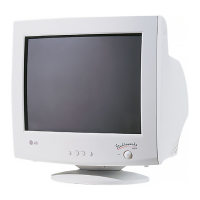
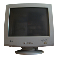
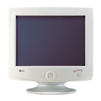
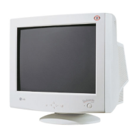
1. PICTURE TUBE
Size : 15 inch (Flat Square Tube)
DefIection Angle : 90°
Neck Diameter : 29.1 mm
Dot Pitch : 0.28 mm
Face Treatment : AR-ASC (Anti-Reflection and
Anti-Static Coating)
Low Radiation : MPR-II
2. SIGNAL
2-1. Horizontal & Vertical Sync
1) Input Voltage Level: Low= ≤0.8V, High= ≥2.0V
2) Sync Polarity : Positive or Negative
2-2. Video Input Signal
1) Voltage Level : 0 ~ 0.7 Vp-p
a) Color 0, 0 : 0 Vp-p
b) Color 7, 0 : 0.467 Vp-p
c) Color 15, 0 : 0.7 Vp-p
2) Input Impedance : 75 Ω
3) Video Color : R, G, B Analog
4) Signal Format : Refer to the Timing Chart
2-3. Signal Connector
15-pin D-Sub Connector (Attached Type)
2-4. Scanning Frequency
Horizontal : 30 ~ 61 kHz
Vertical : 50 ~ 120 Hz
3. POWER SUPPLY
3-1. Power Range
AC 100~240V (Free Voltage), 50/60Hz, 1.5A Max.
3-2. Power Consumption
4. DISPLAY AREA
4-1. Active Video Area :
• 285 x 215 mm (11.22" x8.46") - Max Image Size
• 270 x 200 mm (10.63" x 7.87") - Preset Image Size
4-2. Display Color : Full Colors
4-3. Display Resolution : 1024 x 768 / 75Hz
(Non-Interlace)
4-4. Video Bandwidth : 78 MHz
5. ENVIRONMENT
5-1. Operating Temperature: 0°C ~ 40°C
(Ambient)
5-2. Relative Humidity : 10%~ 90%
(Non-condensing)
5-3. Altitude : 3,000 m
6. DIMENSIONS (with TILT/SWIVEL)
Width : 356.0 mm (14.01")
Depth : 395.0 mm (15.55")
Height : 371.0 mm (14.60")
7. WEIGHT (with TILT/SWIVEL)
Net Weight : 11.7 kg (25.79 lbs)
Gross Weight : 13.2 kg (29.10 lbs)
CONTENTS
- 2 -
SPECIFICATIONS ................................................... 2
SAFETY PRECAUTIONS ........................................ 3
TIMING CHART ....................................................... 4
OPERATING INSTRUCTIONS ................................ 5
WIRING DIAGRAM ................................................. 6
BLOCK DIAGRAM ................................................... 7
DESCRIPTION OF BLOCK DIAGRAM.....................8
ADJUSTMENT ........................................................ 9
TROUBLESHOOTING GUIDE .............................. 11
EXPLODED VIEW................................................... 21
REPLACEMENT PARTS LIST ............................... 23
PIN CONFIGURATION........................................... 28
SCHEMATIC DIAGRAM......................................... 30
PRINTED CIRCUIT BOARD................................... 32
SPECIFICATIONS
MODE
NORMAL (ON)
STAND-BY
SUSPEND
OFF
H/V SYNC
ON/ON
OFF/ON
ON/OFF
OFF/OFF
POWER CONSUMPTION
less than 63 W
less than 15 W
less than 15 W
less than 5 W
LED COLOR
GREEN
AMBER
AMBER
 Loading...