Do you have a question about the LG StudioWorks 700B and is the answer not in the manual?
Details of the monitor's picture tube specifications, including size, deflection angle, and neck diameter.
Specifications for video input signals, including voltage levels, impedance, and connector types.
Details on the monitor's input power range, voltage, and current consumption.
Information on active video area, preset image sizes, display color, resolution, and bandwidth.
Operating temperature, relative humidity, and maximum altitude specifications.
Physical dimensions of the monitor including width, depth, and height with tilt/swivel.
Net and gross weight specifications for the monitor in kilograms and pounds.
Identifies critical safety components and provides general warnings for servicing the monitor.
Precautions regarding high voltage circuits, lead dress, and fire hazards during service operations.
Guidelines for measuring high voltage and steps to prevent X-radiation exposure.
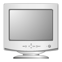
Description of the monitor's front panel buttons and their respective functions.
Step-by-step instructions for removing the monitor's back cover and tilt/swivel mechanism.
Procedure for safely detaching the main chassis assembly from the front cabinet.
Explains the function of the line filter for suppressing noise on the power input line.
Details the degaussing circuit, its components, and operation for color purity.
Describes the operation of the switching mode power supply unit, including input and output.
Explains the mechanism to prevent X-radiation by monitoring high voltage levels.
Overview of the microprocessor's role in controlling monitor functions and OSD.
Description of the circuit generating horizontal and vertical scan pulses from sync signals.
Details the DC to DC converter used for voltage conversion in the deflection circuit.
Explains the circuit that corrects side-pincushion and trapezoid distortion of the screen.
Description of the circuit responsible for generating horizontal deflection current for the yoke.
Details the high voltage generation circuit and the flyback transformer's role.
Explanation of the circuit designed to correct horizontal linearity issues.
Description of the circuit responsible for generating vertical deflection current for the yoke.
Explains the circuit for maintaining consistent focus across the entire screen.
Details the blanking circuits for retrace elimination and brightness control.
Describes the circuit that corrects screen image tilt by supplying a signal to the tilt coil.
Explains the pre-amplification stage for incoming analog video signals.
Details the video output amplification stage that drives the CRT cathode.
Overview of adjustment procedures, requirements, and the necessary alignment tools.
Instructions for performing automatic degaussing and manual degaussing via OSD.
Detailed steps for various calibration procedures, including B+ voltage and factory modes.
Procedures for adjusting white balance, color, and screen luminance using alignment tools.
Procedure for writing and confirming Extended Display Identification Data (EDID).
Steps for adjusting the screen focus by manipulating controls on the Flyback Transformer (FBT).
Diagnostic flowchart for troubleshooting issues where the monitor does not power on.
Diagnostic flowchart for troubleshooting the absence of any display output or characters.
Diagnostic flowchart for troubleshooting issues where no display image (raster) appears.
Diagnostic flowchart for troubleshooting problems related to horizontal picture deflection.
Diagnostic steps for identifying and resolving horizontal linearity distortion issues.
Diagnostic flowchart for troubleshooting problems related to vertical picture deflection.
Diagnostic flowchart for troubleshooting issues with the On-Screen Display (OSD) functionality.
Diagnostic steps for troubleshooting Display Power Management (DPM) mode failures.
Diagnostic flowchart for troubleshooting issues with the monitor's degaussing function.
Diagnostic flowchart for troubleshooting problems related to image tilt or rotation.
Pin description and diagram for the M24C08 serial I2C BUS EEPROM chip.
Pin description and block diagram for the TDA4867J Philips deflection controller IC.
Pin description and block diagram for the TDA4841PS Philips video processing IC.
Illustrations showing the component and solder sides of the monitor's control board.
Illustrations showing the component and solder sides of the monitor's main board.
| Screen Size | 17 inches |
|---|---|
| Maximum Resolution | 1280 x 1024 |
| Dot Pitch | 0.27 mm |
| Input Connectors | VGA |
| Viewable Image Size | 16 inches |
| Horizontal Scan Rate | 30-70 kHz |
| Vertical Scan Rate | 50-160 Hz |
| Aspect Ratio | 4:3 |
| Display Type | CRT |