Do you have a question about the LG StudioWorks 700E and is the answer not in the manual?
Details on the monitor's picture tube, signal inputs, and power supply specifications.
Information on display area, environmental conditions, and physical dimensions including weight.
Highlights critical safety components, general servicing safety, and fire/shock hazard prevention.
Discusses implosion protection, X-radiation prevention, and necessary precautions during service.
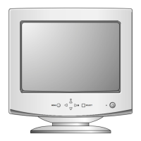
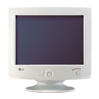
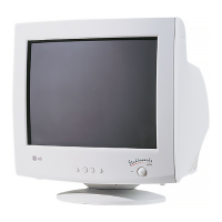
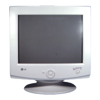
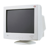
Explains the operation of the monitor's front control panel buttons and their functions.
Step-by-step guide for removing the monitor's tilt/swivel, back cover, and main chassis assembly.
Describes SMPS, X-ray protection, Micom, and horizontal/vertical oscillation circuits.
Explains DC to DC converter, correction circuits, deflection outputs, and video amplifier functions.
Details the image rotation circuit and blanking/brightness control functions.
Overview of adjustment needs, degaussing, and preliminary B+ voltage checks.
Procedures for adjusting high voltage, factory presets, and white balance settings.
Steps for adjusting drive signals, inputting EDID data, and performing focus adjustments.
Flowcharts for diagnosing no power, no character, and no raster problems.
Flowcharts for troubleshooting horizontal/vertical deflection, linearity, and OSD problems.
Flowcharts for diagnosing DPM, degaussing, and tilt/rotation malfunctions.
Details pin configurations and functions for M24C08 EEPROM and TDA4867J IC.
Provides the pinout for the TDA4841PS IC and its associated block diagram.
Shows component and solder sides of the monitor's control and main circuit boards.
| Screen Size | 17 inches |
|---|---|
| Viewable Image Size | 16 inches |
| Max Resolution | 1280 x 1024 |
| Recommended Resolution | 1024 x 768 |
| Aspect Ratio | 4:3 |
| Panel Type | CRT |
| Horizontal Frequency | 30-70 kHz |
| Vertical Frequency | 50-160 Hz |
| Input Signal | Analog RGB |
| Input Connector | 15-pin D-sub |
| Power Consumption | 90W |
| Compliance | UL, CSA, FCC |