Do you have a question about the LG StudioWorks E700B and is the answer not in the manual?
Details on the picture tube size, deflection angle, dot pitch, and signal input types.
Information on power range, consumption, and active display area dimensions.
Operating environment, dimensions, and weight of the monitor.
Warnings about replacing safety-critical parts and preventing X-radiation exposure.
Precautions for fire hazards, electrical shock, and CRT implosion protection.
General safety advice, including tool usage and degaussing coil connection.
Table detailing timing parameters for video and sync signals across different modes.
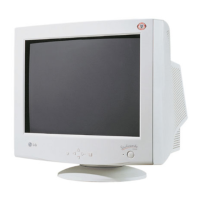
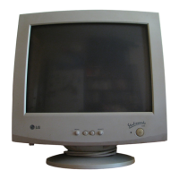
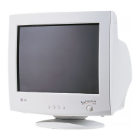
Identification of front and rear panel controls and indicators.
Explanation of the function of each button on the control panel.
Visual representation of the internal wiring connections within the monitor.
Step-by-step guide for removing the monitor's back cover and main chassis.
High-level diagram illustrating the main functional blocks of the monitor.
Descriptions of power supply, X-ray protection, and microprocessor circuits.
Explanations for deflection, high voltage, and timing pulse generation circuits.
Descriptions of blanking, image rotation, and video signal amplification circuits.
Overview of pre-adjustment requirements, tools, and general steps.
Procedures for adjusting B+ voltage, high voltage, and factory presets.
Steps for calibrating white balance, loading EDID data, and adjusting focus.
Diagnostic steps for 'No Power' and 'No Character' issues.
Troubleshooting for 'No Raster' and 'No Horizontal Deflection' faults.
Diagnostic steps for vertical deflection and horizontal linearity problems.
Troubleshooting for OSD, DPM mode, and degaussing function failures.
Diagnostic steps for tilt/rotation and horizontal linearity issues.
Diagram showing the physical arrangement of monitor components.
List of parts identified in the exploded view diagram.
Comprehensive list of replacement part numbers and descriptions.
Pin configuration and internal block diagram for the S3P863A microcontroller.
Technical details for LM1269 video amplifier and LM2480 bias clamp ICs.
Data for EEPROM, TDA4866J deflection booster, and LM2469 CRT driver ICs.
Pinout, features, and block diagram for the TDA4857 deflection controller.
The full circuit schematic for the color monitor.
Layout diagrams for the printed circuit boards (component and solder sides).
| Screen Size | 17 inches |
|---|---|
| Display Type | CRT |
| Maximum Resolution | 1280 x 1024 |
| Refresh Rate | 85 Hz |
| Horizontal Refresh Rate | 30 - 85 kHz |
| Vertical Refresh Rate | 50 - 160 Hz |
| Bandwidth | 110 MHz |
| Input Connector | 15-pin D-sub |
| Power Consumption | 80 W |
| Dimensions (WxHxD) | 16.7 x 15.5 x 16.1 inches |
| Aspect Ratio | 5:4 |
| Panel Type | CRT |
| Viewable Size | 16 inches |
| Input Signal | Analog RGB |
| Input Connectors | VGA (15-pin D-Sub) |