Do you have a question about the LG StudioWorks 773N and is the answer not in the manual?
| Screen Size | 17 inches |
|---|---|
| Viewable Size | 16 inches |
| Max Resolution | 1280 x 1024 |
| Recommended Resolution | 1024 x 768 |
| Panel Type | CRT |
| Aspect Ratio | 4:3 |
| Horizontal Frequency | 30-70 kHz |
| Vertical Frequency | 50-160 Hz |
| Input Signal | Analog RGB |
| Input Connector | 15-pin D-sub |
| Weight | 35.3 lbs |
| Power Consumption | 80 W |
Critical components important for safety must be replaced with specified parts.
Perform service work only after being familiar with safety checks and servicing guidelines.
Use isolation transformer, check lead dress, reinstall protective devices, inspect soldering.
Measure high voltage to ensure it's at the factory recommended level.
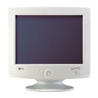
Overview of front and rear views, including power and signal connections.
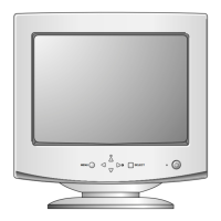
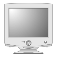
Description of the monitor's control buttons and their functions.
Illustrates the electrical connections within the monitor.
Steps to remove the back cover and tilt/swivel base.
Procedure for safely removing the main chassis assembly.
Visual representation of the monitor's internal circuitry and signal flow.
Describes SMPS, DC-DC converter, High Voltage, and Deflection circuits.
Covers Micom, Sync processing, Blanking, and OSD control.
Details Pincushion, Linearity, and X-ray protection circuits.
Corrects screen tilt by adjusting the tilt coil.
Pre-amplifies and amplifies video signals for the CRT.
Includes required tools, warm-up, and degaussing steps.
Procedures for setting B+ voltage and CRT high voltage.
Steps for factory mode, size, position, and geometric adjustments.
Adjusting white balance, color bias, and luminance levels.
Procedure for inputting EDID data for monitor identification.
Steps to adjust the CRT focus for optimal sharpness.
Step-by-step guide to diagnose and resolve no-power issues.
Diagnosing issues when no characters or video are displayed.
Troubleshooting steps when no raster is visible on the screen.
Diagnosing issues causing only a vertical line on the screen.
Troubleshooting horizontal linearity problems.
Diagnosing issues causing only a horizontal line on the screen.
Troubleshooting issues with the On-Screen Display menu.
Diagnosing issues related to Display Power Management modes.
Troubleshooting the degaussing coil and related circuits.
Diagnosing issues with screen tilt and rotation adjustments.
Visual representation showing the assembly of monitor components.
Comprehensive list of parts with reference numbers and descriptions.
List of replaceable components with part numbers and specifications.
Pinout and function details for the TDA4866J deflection booster.
Pinout and function details for the M24C08 serial I2C bus EEPROM.
Visual representation of the STR-G8644D block diagram and pin connections.
Pinout and function details for the TDA4857 autosync deflection controller.
Detailed electrical circuit diagrams of the monitor's internal workings.
Component and solder side views of the control PCB.
Component and solder side views of the main PCB.