modbus-rtu iS5 manual.doc
3
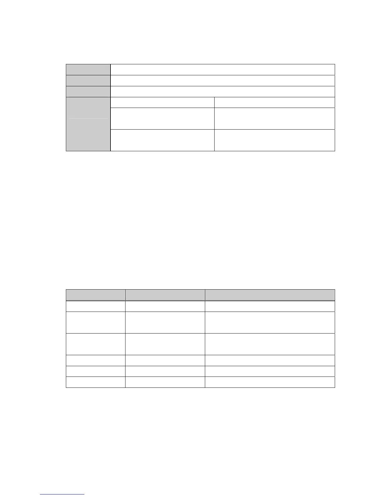
3.2. Status LED
CPU LED
Indicates normal operation of the board when blinking once per second.
RXD LED
Receiving 485 signal
TXD LED
Responding to 485 signal
On and Off intermittently Wrong DATA received (Normal operating)
Blinking with CPU LED at the same
time
DPRAM communication fault
ERR LED
Blinking with CPU LED in an
opposite way
Network Connection TimeOut <I/O-49>
elapsed
4. INSTALLATION
1. Connect the option board to the inverter control board using each connector on the board (See the
Figure 1).
2. Double check the board is firmly installed to the board and then apply the inverter power.
3. When power ON, CPU LED is blinking per second after all LEDs blink one after another.
4. If “CPU LED” is not blinking, turn off the inverter power swiftly (if not, inverter and the board may get
damaged.) and check for the proper installation of the board. If the problem persists, contact LG
distributor.
5. Check ModBus-RTU is displayed in <COM-01>.
6. Set the parameters as below when the above steps are all done.
Parameter code Display Setting Value
< COM-01 > Opt B/D MODBUS displayed automatically
< COM-02 > Opt mode
Set the Command controlled via
communication
< I/O- 46 > Inv. number
1~31
(Verify the assigned number is not duplicated)
< I/O- 47 > Baud-rate 9600 bps (Factory default)
< I/O- 48 > Lost command (Note1) User setting
< I/O- 49> TimeOut (Note 1) 0.1 sec (Factory default)
Note 1) it is used for Emergency Stop when communication between inverter and master is not done
properly. It is activated when communication is not done even once for the set time. It means remote
controlling of inverter is not done. Set this value for safety
7. Turn off the inverter power for the connection of the Converter when step 6 is finished.
8. if the inverter is to be placed at the end of the network trunk line, install a jumper at JP1 on the
Modbus card to enable the termination resistor.
 Loading...