modbus-rtu iS5 manual.doc
4
5. TROUBLE SHOOTING
If communications cannot be established with the drive, there are four LEDs on the Modbus card to aid in
troubleshooting. The CPU LED should blink once per second to indicate that the modbus card is interfacing
with the inverter main PCB properly. The RXD LED should blink each time a properly formed Modbus
message is received that is addressed to the inverter. The RXD LED will not blink when messages are
received that are addressed to other inverters or devices. The TXD LED should blink each time the inverter
responds to a Modbus message. The ERR LED indicates either an invalid request was received or there is a
problem with the Modbus card itself. The ERR LED should never light.
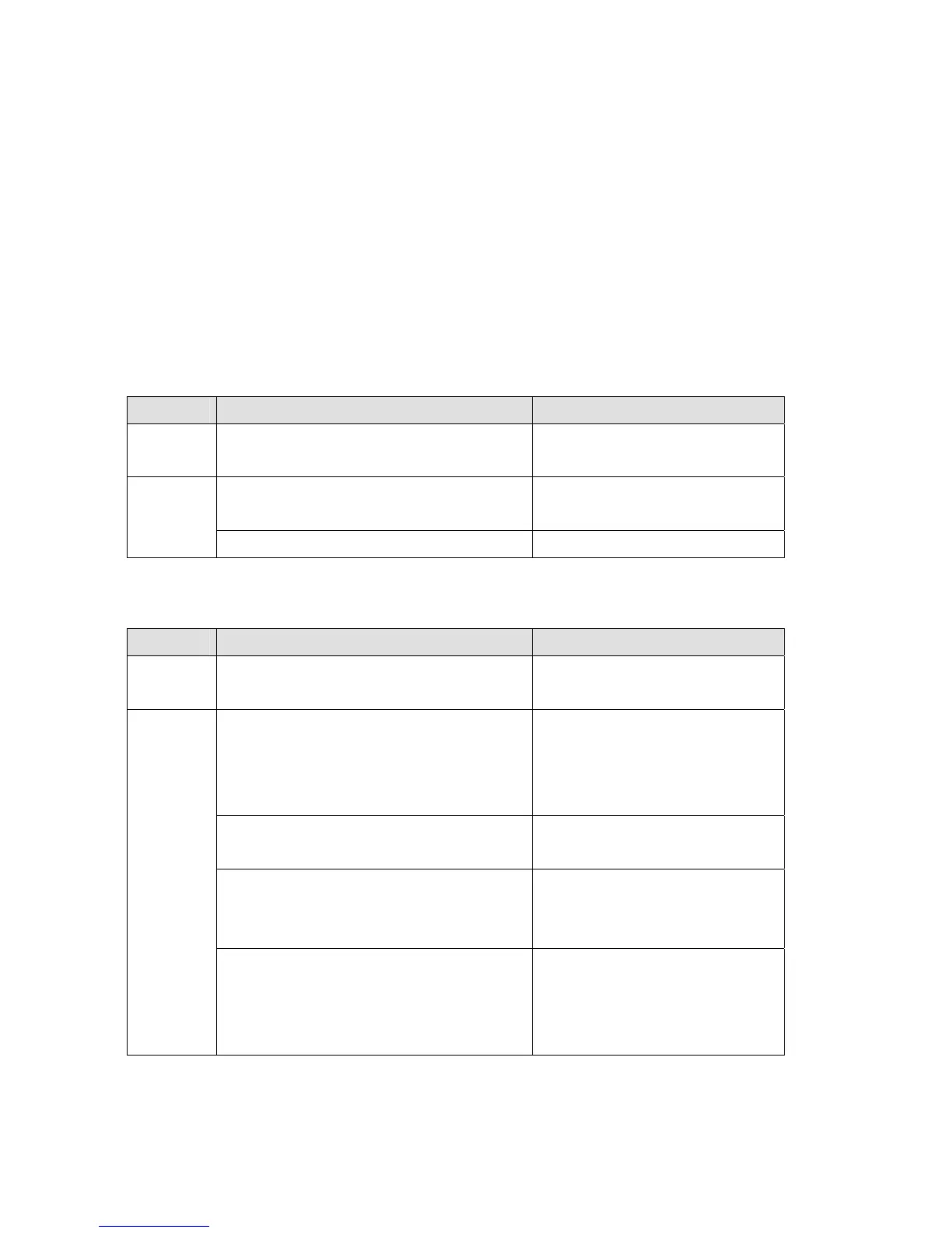
5.1.1. CPU LED
State Indicates Corrective measures
Blinking Card is installed properly and working
normally
Card is not installed properly Verify that the card is installed
properly
Off
Inverter is not operating normally Verify that the inverter has power
5.1.2. RXD and TXD LEDs
State Indicates Corrective measures
Blinking Card is functioning normally and receiving and
sending messages
Incorrect Modbus connection to the card Verify that the Low signal is
connected to terminal N and the
High signal is connected to terminal
P
Master is not polling Verify that the master (PLC or PC) is
polling the inverter.
Incorrect baud rate setting Verify that the baud rate (I/O47) is
set to match the baud rate of the
inverter.
Off
Incorrect byte format The inverter communicates using 8
data bits, 1 stop bit and no parity
bits. Verify that the master is set to
the same.
 Loading...