4. EDID Data Edit Using Service software Program
4.1 Read and Modify EDID Data
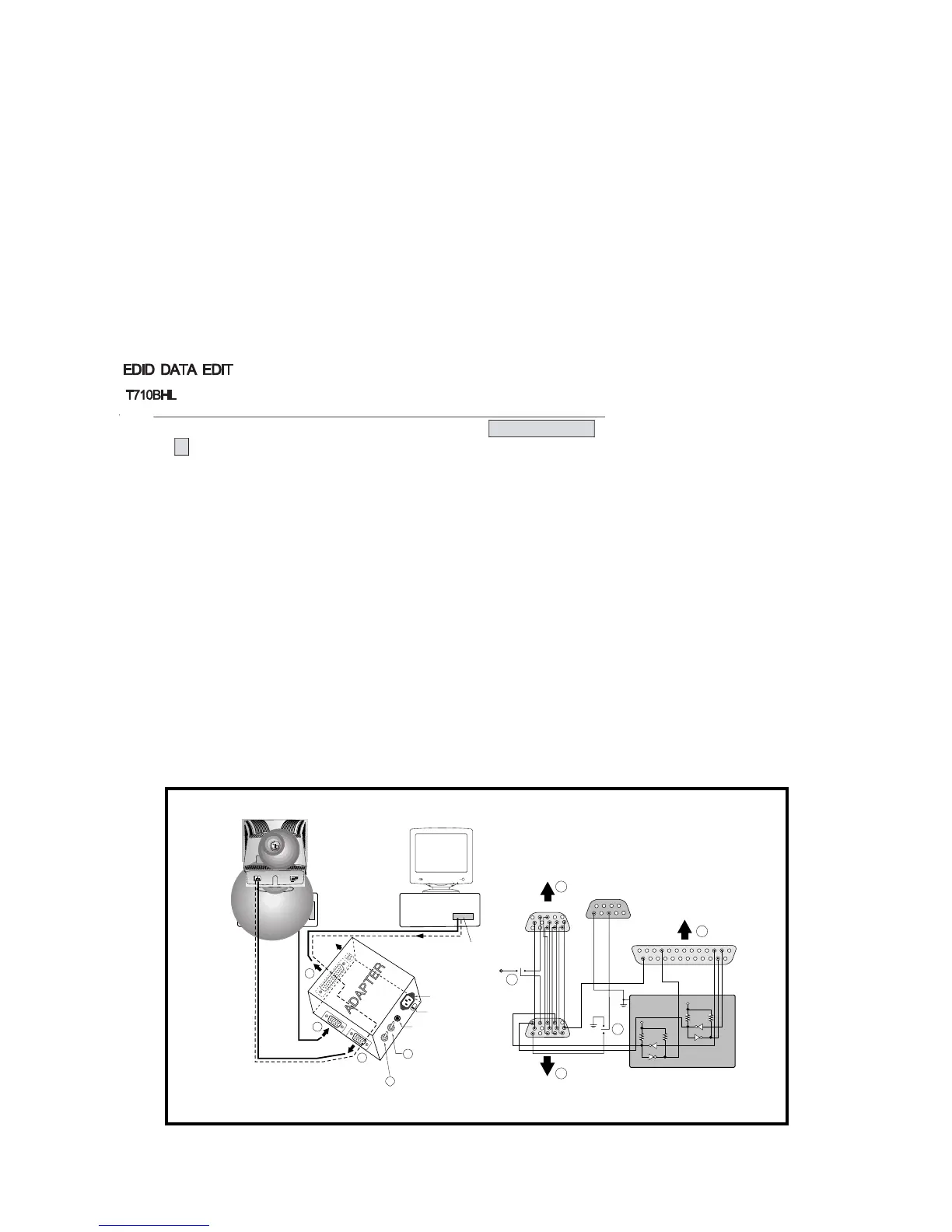
1) Connector the monitor and adjust device as Figure1
2) Display color 15,0 cross hatch pattern at Mode 4.
3) Use EDIT – MODEL SEL. command to select the right model info file.
4) Use EDIT – EDID INFO command and return to read the EDID Data.
5) Modify the EDID Data if needed and using F10 to save the change and exit.
4.2 Write EDID Data.
1) Display color 15,0 cross hatch pattern at Mode 4.
2) Use EEPROM -- Write EDID command and confirm
“EDID Write OK!!” message of monitor.
3) Exit from the alignment program.
4) Power switch OFF/ON for EDID data save.
- 18 -
000102030405060708090A0B0C0D0E0F
00|00FFFFFFFFFFFF001E6D6643*01000000
10|**010E0103182118B5EAF629A253479925
20|10484CFFFE803159714F455961598180
30|814A01010101EA240060410028303060
40|130036E61000001E000000FD0032A01E
50|470B000A202020202020000000FC0054
60|37313042480A202020202020000000FC
70|000A20202020202020202020202000***
- 18 -
220
IB M
C ompatible P C
P AR ALL E L P OR T
P ower inlet (required)
P ower LE D
S T S witch
P ower S elect S witch
(110V /220V )
C ontrol L ine
No
t u
s
e
d
R S 2
3
2
C
P A
R AL
L
E L
V
-
S YN
C
P
O
WE
R
S
T
V
G S
M
ON IT
OR
E
V-S ync On/Off S witch
(S witch mus t be ON .)
F
A
B
C
E
F
A
B
C
15
10
5
5
69
1
1
1
14
13
25
6
5V
5V
5V
4.7K
4.7K
4.7K
74LS 06
74LS 06
OF F ON
OF F
ON
11
VIDE O
S IG NAL
G E NE R AT OR
Figure 1. Cable Connection Figure 1. Cable Connection
T710BL
0 1 2 3 4 5 6 7 8 9 A B C D E F
00 FF FF FF FF FF FF 00 1E 6D #65 #43 *01 *01 *01 *01
**01 ***DE 01 03 18 21 18 B5 EA F6 29 A2 53 47 99 25
10 48 4C FF FE 80 31 59 71 4F 45 59 61 59 81 80
81 4A 01 01 01 01 EA 24 00 60 41 00 28 30 30 60
13 00 36 E6 10 00 00 1E 00 00 00 FD 00 32 A0 1E
47 0B 00 0A 20 20 20 20 20 20 00 00 00 FC 00 54
37 31 30 42 0A 20 20 20 20 20 20 20 00 00 00 FC
00 0A 20 20 20 20 20 20 20 20 20 20 20 20 00 **
 Loading...