Do you have a question about the LG WD-1438RD and is the answer not in the manual?
Lists features like automatic wash-dry, intelligent wash system, direct drive, child lock, low noise, and auto restart.
Explains how fuzzy logic determines optimal washing time by sensing water temperature and laundry amount.
Describes the use of a pressure sensor for water level detection and control in the tub.
States that the door cannot be opened during operation or when the door lock light is illuminated.
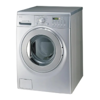
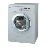
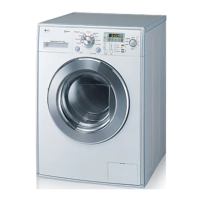
Identifies major parts of the washing machine and lists included accessories like inlet hose and spanner.
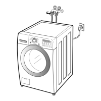
Details steps for standard installation: removing transit bolts, placing on a firm surface, and adjusting leveling feet.
Describes the wash program selector, LED display, water temperature selector, and buttons like Start/Pause, Intensive, Rinse Hold.
Explains Time Delay, Spin button, Power button, Child-Lock, Rinse+, Pre Wash, and Dry functions.
Advises caution regarding electric shock and voltage checks during troubleshooting procedures.
Outlines the procedure to enter QC Test Mode and lists checking points for various operations and their display statuses.
Explains how to check the water level frequency by pressing the Rinse Hold button and its unit of measurement.
Details how to check thermistor temperatures in the tub and dry duct using button combinations.
Lists common error codes (IE, DE, FE, PE, UE, LE, CE, dHE), their symptoms, and potential causes.
Provides troubleshooting for common issues like no power, water inlet, door, and drain problems with diagnostic flow.
Offers detailed diagnostic flowcharts for various faults including power, water supply, detergent, sound, heating, drain, spin, and dry system issues.
Details steps for disassembling the control panel and dispenser assembly, including removing the top plate and panel.
Provides instructions for disassembling inlet valve, lower cover, door, and gasket, covering component removal and hose management.
Guides disassembly of motor components (rotor, stator), pump, heater, and thermistor, including cautions for removal.
Explains disassembling door lock switch and removing foreign objects stuck between the drum and tub.
Details the process for removing the dry duct assembly, dry fan, heater, thermostat, and condensing duct.
Shows an exploded view with part numbers for the main cabinet assembly components.
Presents an exploded view of the control panel and dispenser assembly, labeling various parts.
Displays an exploded view of the drum and tub assembly, identifying internal components and their positions.
Shows an exploded view of the dryer components, including the fan, heater, and ducting, with part references.
| Load Type | Front Load |
|---|---|
| Spin Speed | 1400 RPM |
| Energy Rating | A+++ |
| Noise Level (Washing) | 54 dB |
| Color | White |
| Inverter Motor | Yes |
| Smart Diagnosis | Yes |
| Child Lock | Yes |
| Delay Start | Yes |
| Quick Wash | Yes |
| Type | Washer |
| Dimensions (HxWxD) | 850 x 600 x 600 mm |
| Water Consumption | 56 L |