Do you have a question about the LG WM3700H A /01 Series and is the answer not in the manual?
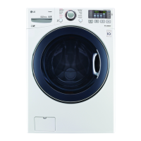
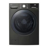
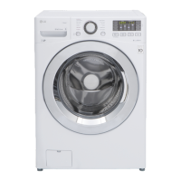
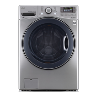
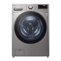
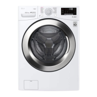
Details the key features of the washing machine, including capacity, motor, door, and smart functions.
Explains how the washing time is optimized using water temperature, selected temperature, and load size.
Describes how the pressure sensor controls water level in the tub for washing.
Details the operation of the door lock and unlock mechanism during cycles.
Lists conditions under which the washing machine door cannot be opened.
Explains how to activate and deactivate the child lock feature for safety.
Describes the NFC Tag On function for smartphone connectivity and features.
Details the steps for standard installation, including bolt removal, surface, and leveling.
Explains the features and layout of the washing machine control panel.
Details the various option buttons and their functions like Pre Wash, Delay Wash, Child Lock.
Explains how to adjust water temperature, spin speed, soil level, and signal volume.
Provides a guide to different wash cycles, fabric types, and recommended settings.
Describes special functions like Child Lock, Fresh Care, Remote Start, and Wi-Fi Connect.
Details the step-by-step explanation of each washing process from start to finish.
Provides critical safety warnings for performing test modes on the appliance.
Explains the procedure and steps for conducting the load test mode.
Guides on how to check the water level frequency using specific button combinations.
General safety precautions to be observed during troubleshooting procedures.
Lists common error codes, their symptoms, and potential causes for diagnosis.
Provides a step-by-step troubleshooting guide for specific error codes like Inlet Valve Error.
Troubleshooting steps for addressing a drain error, checking pump and connections.
Troubleshooting guide for locked motor errors, checking connectors, rotor, and stator.
Steps to diagnose and resolve door open errors, checking switches and connections.
Troubleshooting for unbalance errors, focusing on load distribution and installation.
Guide to resolve overflow errors, checking water level frequency and inlet valve.
Troubleshooting steps for pressure sensor errors, checking connectors and resistance.
Guides on preparing the appliance and smartphone for the Tag On function.
Details the testing procedure and results for the line filter assembly.
Explains the function and testing of the door lock switch assembly.
Describes the stator assembly function and provides test points and results.
Details the pump motor assembly, its function, and testing procedures.
Explains the inlet valve assembly function and provides test points and resistance values.
Details the thermistor assembly function and provides test points and resistance values.
Provides step-by-step instructions for disassembling the control panel assembly.
Instructions for safely disassembling the main PCB assembly.
Step-by-step guide for disassembling the detergent dispenser assembly.
Instructions on how to disassemble and remove the noise filter.
Detailed steps for disassembling the washing machine's cabinet cover.
Instructions for disassembling the washing machine door and hinge.
Steps for removing and replacing the door lock switch assembly.
Instructions for disassembling the water pump assembly and its related parts.
Guide to disassembling the motor and damper components.
Exploded view diagram of the cabinet and control panel assembly components.
Exploded view of the drum and tub assembly, showing internal parts.
Exploded view of the dispenser assembly and its components.
| Type | Front Load Washer |
|---|---|
| Capacity | 4.5 cu. ft. |
| Energy Star Certified | Yes |
| Spin Speed | 1300 RPM |
| Number of Wash Programs | 14 |
| Steam Technology | Yes |
| Smart Diagnosis | Yes |
| Allergiene Cycle | Yes |
| TurboWash | Yes |
| Width | 27 inches |
| Height | 39 inches |
| Color | White |