Operation Manual of Elevating Work Platform
40
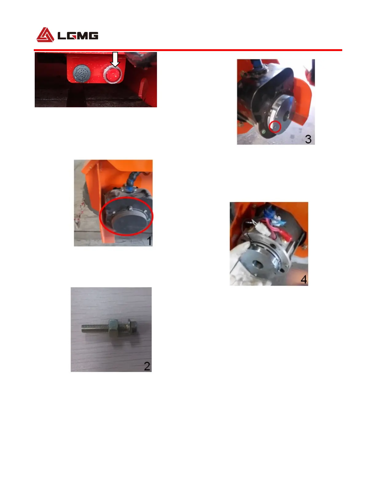
4) If system voltage is lower than 10 v,
according to the following operation.
①Unscrew the drive motor end cover;
②Screw the M6 nut into the M6*25 bolt, see
Figure2 below;
③ Screw the M6*25 bolt into the screw holes in
the brake disc, see Figure3 ;
④Using a wrench to turn the nut counter-
clockwise. When the brake clearance is greater
than 0.003in (0.08 mm), the brake is released.
⑤Repeat the above procedure on opposite drive
motor. With both drive motor brake released the
machine can be moved manually.
⑥After moving the machine,reinstall both drive
motors to the original conditions.
 Loading...