Do you have a question about the LGMG AS0808 and is the answer not in the manual?
Explains DANGER, WARNING, and NOTICE signal word meanings.
Manual safety instructions must be followed, national traffic laws are not necessary.
Defines meanings of symbols, color codes, and signs (Red, Orange, Yellow, Blue).
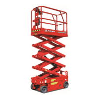
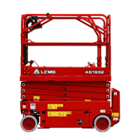
Describes the machine as a self-propelled electric lifting device with a working platform.
Instructions on replacing, cleaning, and maintaining safety signs.
Hazards and safety measures related to electricity and cables.
Risks associated with platform tilt and load capacity limits.
Precautions for ensuring a safe work environment and operation area.
Dangers of abrasions or entrapment due to body parts in moving mechanisms.
Guidelines for operating the machine on slopes and inclines.
Safety measures to prevent falls from the platform.
General danger warnings related to operation and potential hazards.
Precautions to prevent damage to machine components.
Hazards related to flammable materials and operating in explosive environments.
Procedures to prevent damage to the machine itself.
Safety measures to avoid personal injury during operation and maintenance.
Precautions for handling and maintaining batteries safely.
Safety measures to prevent electric shock and burns from electrical sources.
Steps for securing the machine after operation is completed.
Identifies various parts of the machine through a diagram and numbered list.
Illustrates various labels and their locations on the machine.
Lists codes and corresponding product/label descriptions for identification.
Covers main power, lifting, and moving safety during basic operation.
Details on how to steer and drive the machine.
Guidelines for operating the machine with low battery levels.
A flowchart illustrating the sequence of operations for machine control.
Explains the layout and functions of the Platform Control Unit (PCU).
Details on the lever control button and the Main Control (ECU).
Lists alarm codes and their corresponding machine responses.
Tables providing guidance for resolving various operational faults.
Accessing past faults and understanding normal operation modes.
Procedures for moving the platform and controlling lifting operations.
Explains normal operation displays on PCU and ECU.
Interpretation of battery level indicators and charging status.
Operation of emergency stop switches and ground control panel.
Methods for lowering the platform in emergency situations.
Steps to take when machine operation fails or during emergencies.
Procedures for dealing with jammed work panels and tilted equipment.
Steps for inspecting the machine after an accident.
Conditions under which operation is prohibited and fundamental inspection principles.
Detailed steps for inspecting the machine before use.
Conditions for prohibition and basic principles of workstation inspection.
Identifying potential risks and hazards at the workstation.
Conditions for prohibition and basic principles for function testing.
Detailed steps for conducting various function tests.
Testing the functionality of the emergency stop buttons.
Procedures for testing the lift, lower, and initiation functions.
Testing the auxiliary lower function of the platform.
Testing platform control functions and the klaxon horn.
Testing the steering and braking capabilities of the machine.
Further testing of driving and braking functions.
Testing the inclination sensor and exit protector functionality.
Conditions for prohibition and basic principles of operation.
Procedures for emergency stop and lowering the platform.
Instructions for operating the machine from ground and platform controls.
Instructions for steering and driving the machine.
Selecting and adjusting driving speeds.
Guidelines for using the safety support feature.
Steps for extending and retracting the platform and its rails.
Requirements and safety measures for transporting the machine.
Procedures for using forklifts and general lifting guidelines.
Instructions for parking and storing the machine safely.
General compliance, follow-up, and maintenance symbol legend.
Procedures for inspecting batteries and related safety precautions.
How to check and maintain the hydraulic oil level.
Overview of maintenance schedules and reporting requirements.
Forms for recording maintenance and inspection results.
Fields for documenting maintenance and inspection activities.
Introduction to various maintenance checklists (A, B, C).
Detailed steps for inspecting the manual, labels, operation, and function test.
Specific maintenance tasks for 30 days and battery inspection details.
Inspecting cables for damage, wear, and electrical safety.
Inspecting tyres, rims, and the emergency stop system.
Testing key switch, klaxon, and the driving/braking functions.
Procedures for testing driving speed in transport and other statuses.
Testing hydraulic oil and inspecting the ventilation system.
Inspecting chassis drawer locking and lower bound/exit protector switches.
Testing incline sensor and exit protector switch functions.
Procedures for inspecting the upper limit switch.
Steps for testing and calibrating the platform overload system.
Further steps for testing and calibrating the platform overload system.
Procedure for replacing the hydraulic oil tank outlet valve.
Inspecting wear-resistant sliding blocks on scissor arms.
Procedures for testing and changing hydraulic oil.
Electrical schematic for the AS series hydraulic drive system.
Electrical schematic for the AS series electric drive system.
Electrical schematic for the SS series electric drive system.
Hydraulic schematic for the AS0607 model.
Hydraulic schematic for the AS0607E model.
Hydraulic schematic for the AS0607W model.
Hydraulic schematic for the AS0608 model.
Hydraulic schematic for the AS0608E model.
Hydraulic schematic for the AS0808 model.
Hydraulic schematic for the AS0808E model.
Hydraulic schematic for the AS0812 model.
Hydraulic schematic for the AS0812E model.
Hydraulic schematic for AS1012 and AS1212 models.
Hydraulic schematic for AS1012E and AS1212E models.
Hydraulic schematic for the AS1413 model.
Hydraulic schematics for SS0407E, SS0507E, and SS0607E models.
| Platform Capacity | 230 kg |
|---|---|
| Drive Type | Electric |
| Overall Width | 0.81 m |
| Overall Length | 2.48 m |
| Gradeability | 25% |
| Drive Speed (Raised) | 0.8 km/h |
| Drive | 2WD |
| Power Source | 24V DC |
| Maximum Working Load | 230 kg |
| Wheelbase | 1.85 m |
| Tyres | Solid |
| Min. Working Height | 0 m |