Installation
22
2.6.2 Low-Voltage Control Wire Sizing
Low-voltage wiring should be sized to allow a 1 volt maximum drop due to line resistance between the
evaporator and condensing unit. Use NEC Class 1 or 2 wiring according to wire routing conditions
chosen, local codes and application limits in Tables 14 and 15.
2.7 Electrical Data
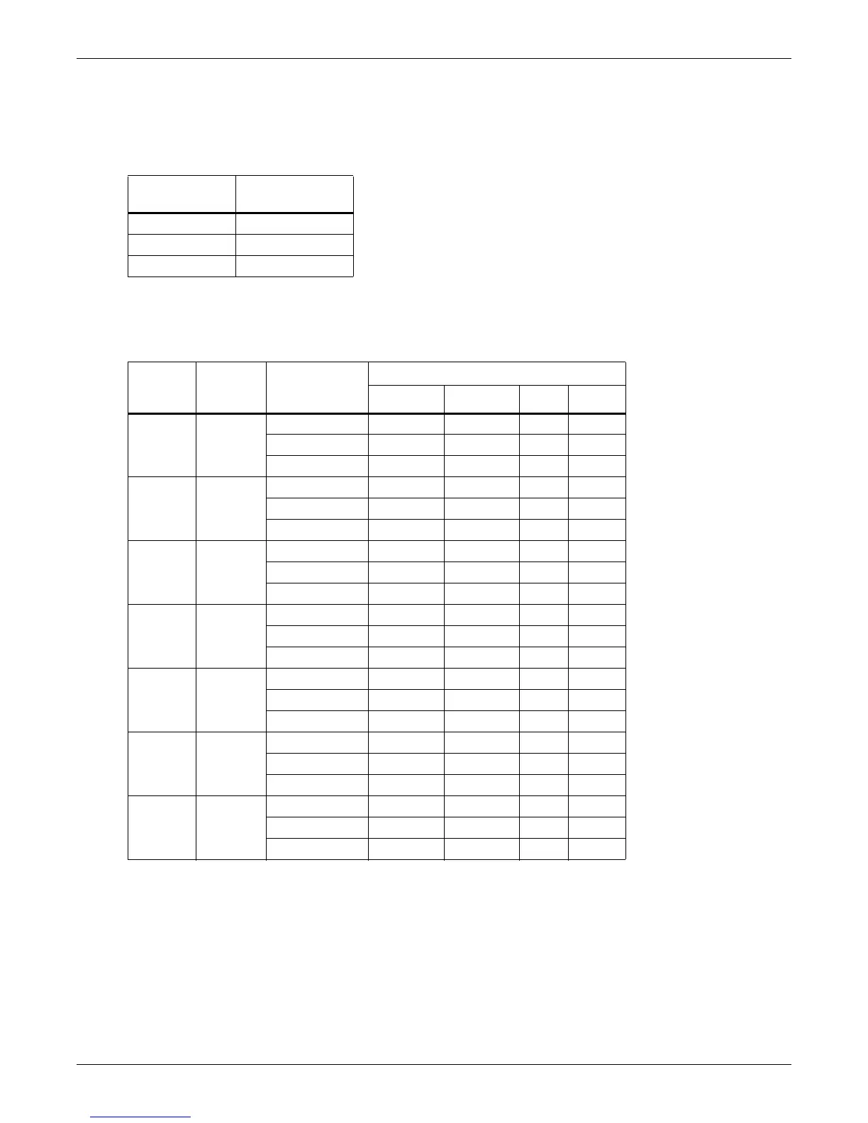
Table 15 Recommended minimum wire size
Max. Distance*
ft. (m)
Min. Wire Gauge
AWG (mm
2
)
50 (15) 20 (0.75)
100 (30) 18 (1.0)
150 (45) 16 (1.5)
* One-way control wire run between outdoor condensing unit and evaporator.
Table 16 Electrical data—Standard sound and ambient models (95°F/35°C) 60Hz
Model #
Nominal
Capacity
Tons
* Electrical
Characteristic
Input Voltage- Phase
208/230-1 208/230-3 460-3 575-3
14 1
FLA 9.1 — — —
WSA 11.0 — — —
OPD 15 — — —
20 1.5
FLA 12.1 — — —
WSA 14.8 — — —
OPD 25 — — —
27 2
FLA 13.4 — — —
WSA 16.4 — — —
OPD 25 — — —
37 3
FLA 18.5 13.4 7.1 5.8
WSA 22.8 16.4 8.7 7.0
OPD 35 25 15 15
42 3.5
FLA — 15.0 7.1 6.0
WSA — 18.4 8.7 7.2
OPD — 30 15 15
67 5
FLA — 24.1 11.7 9.1
WSA — 29.3 14.2 11.1
OPD — 45 20 15
96 8
FLA — 36.2 18.1 13.4
WSA — 41.4 20.6 15.3
OPD — 60 30 20
* FLA = Full Load Amps
WSA = Wire Size Amps (minimum supply circuit current capacity)
OPD = Overcurrent Protection Device (fuse or circuit breaker)