Do you have a question about the Life Fitness CM3 and is the answer not in the manual?
| Brand | Life Fitness |
|---|---|
| Model | CM3 |
| Category | Home Gym |
| Language | English |
Critical safety notice regarding product assembly and use.
Essential guidelines for safe operation and risk minimization.
Lists all necessary tools for assembling the gym system.
Visual guide for measuring bolt lengths during assembly.
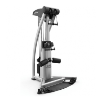
Diagram showing the machine's space occupation with grid.
Specifies the minimum clear space needed around the equipment.
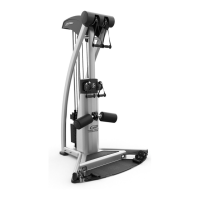
Dimensions when the optional leg press attachment is included.
Detailed instructions for assembling the end of a cable with specific components.
Connects base plates and connector to the front base using specified bolts and nuts.
Attaches the footplate to the front base using a bolt and lock nut.
Connects the rear base to the base connector with bolts and washers.
Attaches the upright to the front base using bolts, washers, and lock nuts.
Connects the right arm and rear base using bolts, washers, and lock nuts.
Connects the left arm and rear base using bolts, washers, and lock nuts.
Attaches both arms to the upright using bolts, washers, and lock nuts.
Shows the correct assembly of weight plates.
Demonstrates the assembly of the head plate.
Inserts guide rods into the rear base and lubricates them.
Slides spacers, cushions, weight plates, and head plate onto guide rods.
Swings guide rods into boom plates and loosely attaches plates to upright.
Tightens all frame connections securely.
Secures the seat/back pad to the seat adjust mechanism.
Secures the three prong knob to the front base.
Inserts the seat adjust assembly into the front base.
Assembles the leg pedestal to the front base using specific hardware.
Detaches and slides long cables through guide bracket eyelets.
Assembles pulleys and plates to boom plates using specified hardware.
Attaches the weight stack pin to the head plate assembly.
Routes the weight stack cable around pulleys in boom plates.
Assembles two pulley plates with a pulley using a bolt and lock nut.
Loops weight stack cable around pulley and attaches it to guide bracket.
Disassembles short cables and turnbuckles from guide cables for later reassembly.
Loops the boom cable around a pulley and attaches it to the guide bracket.
Connects leg cable and pulley to leg pedestal using hardware.
Attaches a pulley to the front base using specified hardware.
Slides guide cables through bracket and reassembles ends with turnbuckles.
Attaches a pulley to base plates with guide cables and spacers.
Loops the leg cable over a pulley and secures it to pulley plates.
Attaches rear guide cables and pulley to base plates using hardware.
Adjusts rear guide cable tension and screws leg cable into pulley bracket.
Routes the arm cable through the left arm and attaches a pulley.
Secures two 3-1/2" pulleys to base plates using bolts and nuts.
Loops arm cable between pulleys and attaches it to the guide bracket.
Routes the arm cable through the right arm and attaches a pulley.
Inserts swivel pulley assemblies into arms and secures them with c-rings.
Attaches quick connects to each end of the arm cable.
Secures the seat pad to the back pad adjustment using bolts and washers.
Attaches the back pad adjustment to the upright using a bolt and lock nut.
Attaches roller pads to the leg pedestal using tubes, washers, and screws.
Attaches roller pads to the seat adjust using tubes, washers, and screws.
Attaches roller pads to the back pad adjustment using tubes, washers, and screws.
Adjusts tension on guard cables using turnbuckles.
Adjusts head plate position and cable slack for optimal performance.
Ensures all jam nuts are securely tightened after adjustments.
Advises on regular cleaning with soapy water and lubricating guide rods.
Recommends daily inspection for loose connections and worn parts.
Prompts users to record model, serial, and purchase details for service.
Outlines lifetime and 3-year limited warranty coverage for parts and frame.
Lists factors that can void the warranty, such as misuse or unauthorized repair.
Details the steps to follow when requesting warranty service.