Page 6
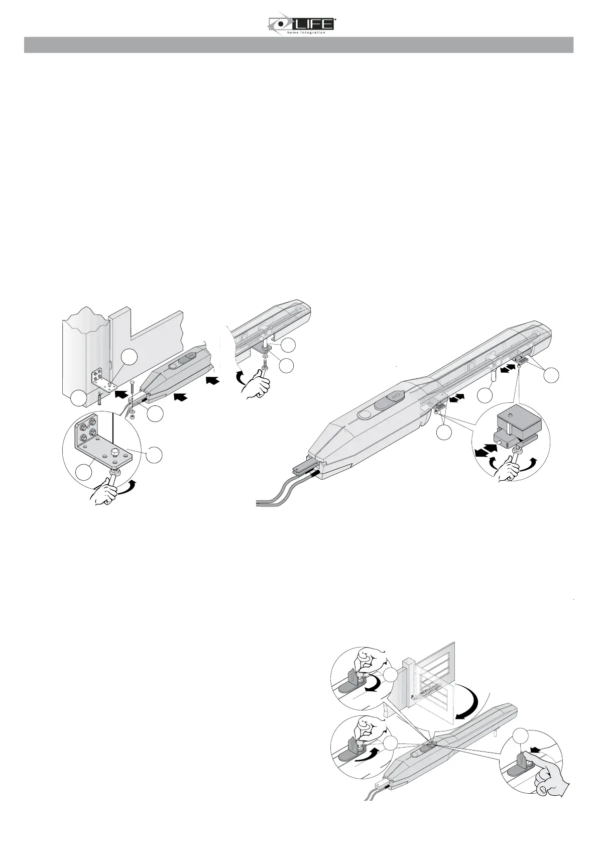
2.4 Positioning the operator and stop plate adjustment
1. Release the operator as indicated in the RELEASING THE OPERATOR chapter.
2. Lift the operator and insert the nut screw bushing support pin (3) into the hole on the front bracket (2).
3. Insert the bushing (4) into the chosen hole on the rear bracket (1) and thread the operator fork (5) on to the bracket, aligning the hole with the
bushing. Fix the whole set with a screw, washer and self-locking nut and tighten.
4. Fix the operator to the front bracket (2) using a screw and washer, and tighten.
5. Manually open and close the gate several times and check that the movement of the leaf is regular and that the operator moves on a plane parallel
to the gate’s plane of movement.
6. Check that the nut screw bushing support (3) slides perfectly on the operator nut screw and that, with the leaf closed and open, there are at least
5 mm between the nut screw bushing support (3) and the closure (6) and opening (7) stop plates.
7. If necessary, use a different hole on the rear bracket and repeat the operations indicated in points 3 and 4. .
’s internal slider, as follows:
lock again by tightening.
lock again by tightening.
or by welding).
10. Release the operator as indicated in the RELEASING THE OPERATOR chapter.
2.5 Releasing the operator
ATTENTION:
.
mechanical unbalance conditions.
This command makes it possible to release the operator transmission and to perform leaf movement manually
. It can be used in the case of a blackout or
system malfunction.
The release is activated using a key, which must be kept in a safe place.
3
6
7
2
3
4
1
5
1
5
a) Lift the lock protection cover (1).
b) Insert the key (2) into the lock and turn clockwise through 360°.
1
2
360°
2
360°