EasyManua.ls Logo

Life RG1 24P User Manual

Life RG1 24P
27 pages
To Next Page IconTo Next Page
Page #1 background imageLoading...
Page #1 background image
ISTRUZIONI E AVVERTENZE PER L’INSTALLAZIONE, L’USO E LA MANUTENZIONE.
INSTRUCTIONS AND WARNINGS FOR INSTALLATION, USE AND MAINTENANCE.
INSTRUCCIONES Y ADVERTENCIAS PARA LA INSTALACIÓN, EL USO Y EL MANTENIMIENTO.
INSTRUÇÕES E ADVERTÊNCIAS PARA A INSTALAÇÃO, USO E MANUTENÇÃO.
INSTRUKCJE I WSKAZÓWKI DOTYCZĄCE MONTAŻU, UŻYTKOWANIA I KONSERWACJI.
3DP0 750 000 - 03/2007
RG1 24P
CENTRALI DI COMANDO PER CANCELLI AD ANTA.
CONTROL UNITS FOR LEAF GATES.
UNIDADES DE CONTROL PARA CANCELAS DE UNA HOJA.
CENTRAIS DE COMANDO PARA PORTÕES DE BATENTE.
CENTRALE STERUJĄCE DO BRAM PRZESUWNYCH.
Question and Answer IconNeed help?

Do you have a question about the Life RG1 24P and is the answer not in the manual?

Life RG1 24P Specifications

General IconGeneral
Ports24
Input Voltage24V DC
Output Voltage24V DC
Number of Outputs24
ProtectionShort circuit, overload

Summary

Declaration of Conformity

Rapid Installation

Leaf Positioning

Position the gate leaf at approximately 50 cm from the closure position.

Phase 2 Power Supply Check

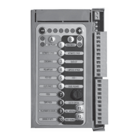
Switch on power and check system LEDs for correct status.

Radio Control Identification (Step Command)

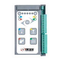
Identify radio control key (F1) for step command operation.

Phase 4 Card Initialisation

Phase 5 Closure Stop Plate Identification

Phase 6 Opening Stop Plate Identification

Phase 7 Speed Identification

Resetting the Control Unit

Wiring and Connections

List of Electric Cables

Details required cables for installation, compliant with IEC 60335.

Electric System Setup

Warnings regarding mains supply connection by authorized personnel.

Control Unit Connections

Instructions for connecting supply, motor, encoder, and accessories.

RG1 24P Board Right Side Diagram

Indicator LEDs

RG1 24P Control Unit Lower Wiring Diagram

Indicator LEDs Details

Starting Up

Keyboard Description

Overview of the control unit keyboard layout and functions.

Radio Control Identification

Procedure for identifying radio controls for step and pedestrian commands.

Radio Control Resetting

Master Radio Control Creation

Initialisation

Using the Master Radio Control

Accessing receiver memory via master remote control for function selection.

System Initialisation Procedure

Initialize the control unit for the specific automation type.

Adjustments

Card Initialisation

Erase previous settings and define automation parameters.

Resetting Travel and Functions

Reset travel limits, function modes, and settings.

Direction, Travel, Speed Identification

Identify gate direction, travel limits, and operational speed.

Resetting Travel

Function Modes

Dead Man Mode

Gate movement requires the 'step' key to be held down.

Semi-automatic Mode

Gate cycles through open, stop, close, stop with each 'step' command.

2-step Automatic Mode

4-step Automatic Mode

4-step Automatic with Stop

Condominium Mode

Functions

Blackout Function

Describes control unit reaction to power failure based on stop plate status.

Pre-flashing Function

Enables 4-second pre-flashing by the light before movement.

Flashing in Pause Function

Enables flashing light operation during pause before auto-closure.

Photo Test Function

Photo 1 Function

Close After Photo Function

Opening Ram Blow

Force Adjustment

Pause Time Setting

Courtesy Light Function

Deceleration in Opening/Closure

Obstacle Detection

Pedestrian Opening

Fuses

Frontal Fuses

Primary 230V fuse for protection against overload.

Card Fuse

Internal fuse (F1) for protecting the electronic board's power supply.

Preset Functions F1 & F2

Allows selection of two standard function parameter settings.

Troubleshooting

Malfunctions Indicated on Control Unit

Lists malfunctions detected by LEDs and flashing lamp, with actions.

Buffer Batteries (Optional)

Battery Installation in GEBOX

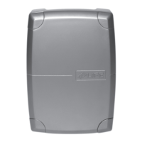
Procedure for installing optional 12V 2Ah buffer batteries in the GEBOX.

Automation Use

Flashing Light Functions

Explains flashing light signals for gate movement and malfunctions.

Automation Malfunction

Indicates malfunctions via flashing light and basic troubleshooting steps.

General Information

Manufacturer Information

Details about LIFE home integration, the manufacturer.

Intended Use

Specifies the RG1 24P control unit's designed purpose and forbidden uses.

Safety Instructions and Warnings

Testing and Trial Run

Testing Procedures

Ensures gate impact force meets standards and checks all functions.

First Usage Requirements

Outlines necessary checks and documentation before initial operation.

Maintenance

Maintenance Instructions and Warnings

Notes on parameter changes, manufacturer's disclaimer, and fitter's responsibility.

Routine Maintenance

Recommends periodic tests by a professional fitter every 6 months.

Demolition and Disposal

Related product manuals