FlexPower Vantage R8 Access Power System - Installation Manua 7
R8 Power Control Accessory Input and Output Wiring
INPUT WIRING
GND GND GND GND
1 2 3 4
GND GND GND GND
5 6 7 8
INPUT 1 - 4 INPUT 5 - 8
GND GND GND GND GND GND GND GND
B2
BR
B1
IN1 IN2 IN3 IN4 IN8IN7IN6IN5
Each input on the R8 / R8P has an “IN” terminal and a “GND”
terminal.
• When using a NO relay contact to activate the input, the
contact is placed across these terminals.
• To use a DC ground or an open collector (transistor) as
an input, connect the ground/open collector to the “IN”
terminal to activate the input. Note that the input source
must be common grounded with the R8/R8P board’s
power source.
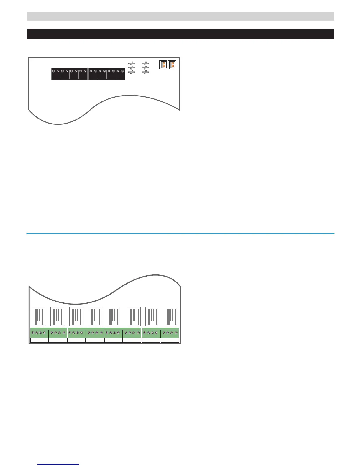
OUTPUT WIRING
NC C N0 COM NC C N0 COM
OUTPUT - 1 OUTPUT - 2
NC C N0 COM NC C N0 COM
OUTPUT - 1 OUTPUT - 2
NC C N0 COM NC C N0 COM
OUTPUT - 1 OUTPUT - 2
NC C N0 COM NC C N0 COM
OUTPUT - 1 OUTPUT - 2
INPUT 1 - 2 INPUT 3 - 4 INPUT 5 - 6 INPUT 7 - 8
Each output on the R8 / R8P has “NC”, “C”, “NO”, and
“COM” terminals.
• When set for a dry contact output, the C, NC, and NO ter-
minals may be used as any relay would. C to NC will have
a connection when the red LED for the zone is not lit. C to
NO will have a connection when the red LED is lit.
I NOTE: To set the output as a dry contact, the yellow and black
jumpers for the zone must be removed and the output diodes must
be cut.
• When set for a voltage output, the terminal use is as
follows:
COM - This is the DC Common for the device being
powered
C - This terminal always has voltage, regardless of
the relay state. This terminal may be used to power
auxiliary devices such as REX or readers.
NC - This output has voltage when the relay is NOT
ACTIVE. This terminal is used for FAIL SAFE locks
NO - This output has voltage when the relay is AC-
TIVE. This terminal is used for FAIL SECURE locks
 Loading...