Do you have a question about the Lifetime MAMMOTH Series and is the answer not in the manual?
Instructions for safely handling and moving the glass backboard during assembly.
Aligning pole sections with stickers and sliding top pole onto middle pole.
Seating pole sections by striking them on a hard surface.
Connecting middle pole to bottom pole, ensuring correct orientation.
Seating poles by striking them on a hard surface, ensuring marks are covered.
Attaching bottom pole to axle and sliding wheels and base frame assembly.
Positioning the base onto the assembled base frame.
Raising the pole assembly until the small axle engages with the base.
Placing rim spacer and attaching left/right rim housings to backboard.
Attaching the rim adapter plate to the backboard.
Sliding rim pin into rim and eye bolt, attaching rim to housing.
Sliding compression spring onto eye bolt and securing with nuts for rim tension.
Attaching lower extension arms to the top pole.
Attaching upper extension arms to the top pole.
Securing the backboard to the extension arms using bolts and nut coupler.
Filling the base with sand or water, with safety warnings.
Anchoring the system to the ground using chains and concrete anchors.
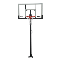
| Backboard Material | Polycarbonate |
|---|---|
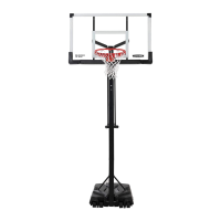
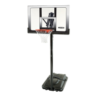
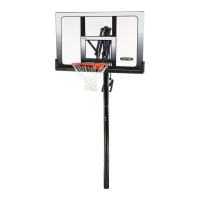
| Backboard Size | 54 inches |
| Category | Basketball System |
| Material | Steel, Polycarbonate |
| Color | Black |
| Warranty | 5 years |