Do you have a question about the Lightspeed Rocket and is the answer not in the manual?
Device compliance with FCC rules, subject to two conditions for interference.
Product is Class A, may cause radio interference in domestic environments.
Product is VCCI Class A compliant; may cause interference in homes.
Perchlorate material handling notice required by California regulations.
Appliance for restricted areas, setup/maintenance by qualified personnel.
Power down appliance properly, unplug AC cord before servicing.
Use correct, certified, grounded power cords with appropriate ratings.
Maintain temperature 10-35°C and humidity 8-90% non-condensing.
Handle batteries carefully to avoid explosion and dispose of them properly.
Disconnect power supply at breaker; prevent ESD damage using proper tools.
Prevent overheating by ensuring proper ventilation and clear airflow.
Use precautions for high voltage; do not work alone; use grounded outlets.
Consider elevated temperature, ensure reduced airflow, and secure mechanical loading.
Address circuit overloading, ensure reliable earthing, and install AC power disconnect.
Verify ship kit includes power cords and rail kit for rack installation.
Follow rail kit instructions; proceed to rear panel connections after rack installation.
Connect Ethernet cable to MANAGEMENT port and LAN, then connect power cords.
Describes LED states for power supply conditions (Output ON/OK, No AC, PS Off, Warning, Critical).
Connect Ethernet cable to MANAGEMENT port and LAN, then connect power cords.
Describes LED states for power supply conditions (Output ON/OK, No AC, PS Off, Warning, Critical).
Connect Ethernet cable to MANAGEMENT port and LAN, then connect power cords.
Describes LED states for power supply conditions (Output ON/OK, No AC, PS Off, Warning, Critical).
Connect Ethernet cable to MANAGEMENT port and LAN, then connect power cords.
Describes LED states for power supply conditions (Output ON/OK, No AC, PS Off, Warning, Critical).
Connect Ethernet cable to MANAGEMENT port and LAN, then connect power cords.
Describes LED states for power supply conditions (Output ON/OK, No AC, PS Off, Warning, Critical).
Connect Ethernet cable to MANAGEMENT port and LAN, then connect power cords.
Describes LED states for power supply conditions (Output ON/OK, No AC, PS Off, Warning, Critical).
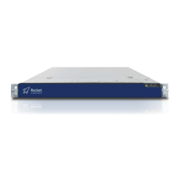
Press the power button on the front right side of the appliance.
Explains bi-color LED states (OFF, GREEN, AMBER) for system status and criticality.
Align bezel, insert right tab into appliance handle, then swing and press left side.
| Brand | Lightspeed |
|---|---|
| Model | Rocket |
| Category | Server |
| Language | English |