Lightspeed Rocket Hardware Installation Guide 11
ID
POST ID
AC Power
Inlets
Video Port
Ethernet
Cable
Local
Area
Network
2
1
Power Cords
Power Good LEDs
USB Ports
Network Interface Connectors
Management
Port
4
Auxilliary
Port
Internal
External
Power Good LEDs
ill
Management
a
e
nt
Exter
Network Interface Connectors
USB Ports
e
nal
Network Interface Connectors
ideo PortV
Inlets
AC Power
ID
Cable
Ether
1
Cable
netEther
Network
eaAr
Local
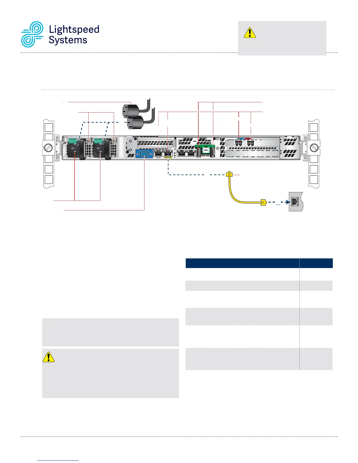
6E. Lightspeed Rocket Web Filter and Traffic Bridge - 10Gb Fiber
Rear Panel Connections
CAUTION
Slide rail/mounted equipment is not
to be used as a shelf or a work space.
NOTE: The server offers redundant, hot-swap capability. The connections
to AC mains should be made in a manner appropriate to local code and
consistent with customer power distribution with or without redundant
sources.
CAUTION
The power supply is hot-swappable only when you have a server with
redundant power supplies installed. If you only have one power supply
installed, before removing or replacing the power supply, you must first
take the server out of service, turn off all peripheral devices connected to
the server, turn off the server by pressing the power button, and unplug the
AC power cord from the server or wall outlet.
Power Supply Condition
Output ON and OK
No AC power to both power supplies
AC present / Only 5VSB on (PS off)
AC cord unplugged or AC power lost; with a second
power supply in parallel still with AC input power
Power supply warning events where the power
supply continues to operate; high temp, high power,
high current, slow fan
Power supply critical event causing a shutdown;
failure, Over Current Protection, Over Voltage
Protection, fan fail
LED State
GREEN
OFF
1Hz Blinking
GREEN
AMBER
1Hz Blinking
AMBER
AMBER
Power Supply Status LED
There is a single bi-color Power Good LED on each power supply
module to indicate power supply status. The LED operation is
defined in the following table.
Step 1 Connect one end of the yellow Ethernet cable into
the Ethernet port labeled MANAGEMENT.
Step 2 Connect the other end of the yellow Ethernet cable
into an available switch port on your Local Area
Network. This port will require Internet access.
Step 3 Please review the latest Lightspeed Systems
Rocket Web Filter Product Manual on the
Lightspeed Systems Community Site at
(
http://community.lightspeedsystems.com/
product-information/documentation/web-filter/
).
Step 4 Connect the power cords.
Step 5 Proceed to Front Panel Operation on page 13.
In normal operation the Power Good LED on Power Supply Module 1
and Module 2 will be SOLID GREEN. If the power is down, both LEDs
will BLINK GREEN.