-2-
⑥ Wi-Fi Antenna Plug (Wi-Fi Model Only)
⑦ QR Scan Button (Wi-Fi Model Only)
1. Press and hold the button for 2–5 seconds to enter the QR
Scan Mode.
2. Press and hold the button for more than 6 seconds to enable
the AP mode.
⑧ DC12V Power Input Jack (DC12V± 10%)
⑨ Live Video Output RCA Jack
⑩ Audio Input 3.5mm Phone Jack
⑪ Audio Output 3.5mm Phone Jack
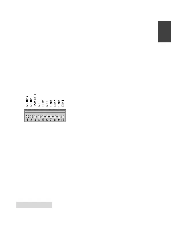
⑫ Alarm In/Out and RS-485 Terminal
⑬ RJ-45 Network Connector and Indicator LEDs
Green (LINK): Network connection. LED remains lit while
connection is in place.
Orange (ACT): Data communications. This LED should continue
to blink.
⑭ Straight Mounting Bracket
○
15
Image Sensor Unit
○
16
RJ-12 Cable
○
17
Wi-Fi Antenna (2.4GHz) (Wi-Fi Model Only)
○
18
Image Sensor Unit (Dome Model Only)
Installation
Main Unit Installation
Please use a screwdriver to fixe the iron plates to the bottom base


 To Next Page