8
Note:
• Before measuring resistance, switch off the power supply of the circuit, and fully
discharge all capacitors.
• If the resistance when probes are shorted is more than 0.5
Ω
, please check if test leads
are loosened or damaged.
• If the resistor is open or over the range, the "OL" symbol will be displayed on the
screen.
• When measuring low resistance, the test leads will produce 0.1
Ω
~
0.2
Ω
measurement
error. To obtain accurate measurement, the measured value should subtract the value
displayed when two test leads are shorted.
• When measuring high resistance above 1 M
Ω
, it is normal to take a few seconds to
steady the readings. In order to quickly obtain steady data, use short test wires to
measure high resistance.
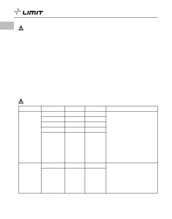
TECHNICAL SPECIFICATION
Accuracy: ± (% of reading + numerical value in least significant digit slot).
Note: Temperature coefficient = 0.1
×
(specified accuracy)
/
°C (<18°C or >28°C)
Function Range Resolution Accuracy Notification
DC Voltage
200 mV 0.1 mV ± (0.7%+3) Overload protection:
250 Vrms (AC/DC)
Input impedance: about l0 M
Ω
.
Results might be unstable
at mV range when no load
Is connected. The value
becomes stable once the load
is connected. Least significant
digit
≤
±3.
Max input voltage: ±250 V,
when the voltage
≥
610 V, "OL"
symbol appears.
2000 mV 1 mV ± (0.5%+2)
20.00 V 0.01 V ± (0.7%+3)
200.0 V 0.1 V ± (0.7%+3)
250 V 1 V ± (0.7%+3)
AC Voltage
200.0 V 0.1 V ± (1.2% +3) Input impedance: about 10 M
Ω
.
Frequency response:
40 Hz
~
400 Hz, sine wave RMS
(average response).
Max input voltage: ±250 V,
when the voltage
≥
610 V, "OL"
symbol appears.
250 V 1 V ± (1.2% +3)
GB