Do you have a question about the Lincoln Electric AIR VANTAGE 500 (AU) and is the answer not in the manual?
| Model | AIR VANTAGE 500 (AU) |
|---|---|
| Output Current Range | 20 - 500 Amps |
| Fuel | Diesel |
| Power Factor | 1.0 |
| Protection Class | IP23 |
| Type | Engine Driven Welding Generator |
| Processes | Stick, TIG, MIG, Flux-Cored |
| Rated Output | 500 Amps |
| Input Power | N/A (Engine-Driven) |
| Engine Power | 24.8 HP |
| Frequency | 50 Hz |
Covers essential safety advice, warnings, and cautions for operating the equipment.
Details California Proposition 65 warnings and hazards related to engine exhaust.
Highlights hazards of arc welding and exposure to electric and magnetic fields.
Addresses electric shock risks and protection from arc rays, with recommended safety measures.
Covers hazards from fumes and gases, and precautions against fire and explosion risks.
Outlines precautions for cylinder safety and Electromagnetic Compatibility (EMC).
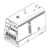
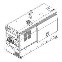
Provides detailed specifications for the engine, welder, compressor, and physical dimensions.
Covers requirements for unit placement, ventilation, and proper storage procedures.
Details procedures for lifting, towing, and considerations for high altitude operation.
Details pre-operation checks for the engine, compressor, fuel, and battery connection.
Describes installation of muffler, spark arrestor, and air cleaner components.
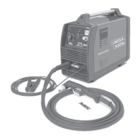
Details routing and connecting welding output cables and machine grounding procedures.
Explains connections for remote controls and setting up standby power systems.
Details the procedure for connecting LN-7, LN-8, LN-742, and LN-15 wire feeders.
Covers connecting the LN-25, NA-3 welding system, and spool guns.
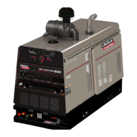
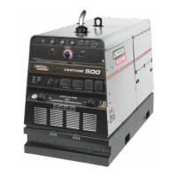
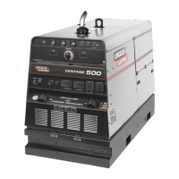
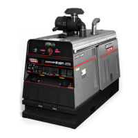
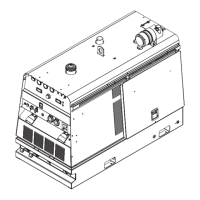
Provides a general description of the unit, its applications, and its compressor/generator functions.
Details the engine controls including the run/stop switch, start button, hour meter, and gauges.
Explains welding mode selector, arc control knob, and output terminals for welding operations.
Describes the controls for auxiliary power, including circuit breakers and receptacles.
Explains Voltage Reduction Devices (VRD) and Reduced Open Circuit Voltage (ROCV) and their operation indicators.
Covers the recommended starting technique and the engine break-in period.
Details operation in Stick and Touch Start TIG modes, including settings.
Details operation for wire welding (CV-WIRE) and arc gouging applications.
Explains how to parallel machines and manage simultaneous welding and auxiliary power loads.
Lists various optional accessories available for enhancing the unit's functionality.
Covers safety, routine checks, and recommended maintenance for the engine and compressor.
Provides detailed instructions for inspecting, cleaning, and replacing engine air cleaner elements.
Details maintenance procedures for fuel filters, cooling system, and safe battery handling.
Covers battery charging procedures and maintenance for the welder and generator components.
Explains the three-step process for using the troubleshooting guide effectively.
Addresses common engine problems such as not cranking, not starting, or shutting down unexpectedly.
Covers troubleshooting issues related to engine idle speed and output control.
Addresses problems with no welding output, loss of control, or lack of auxiliary power.
Presents wiring diagrams for specific machine codes and electrical symbols.
Illustrates the connection diagram for spool guns (K487-25) to the engine welder.
Shows the connection diagram for LN-7 wire feeders and related accessories.
Shows the connection diagram for LN-8 wire feeders.
Illustrates connection diagrams for LN-25 wire feeders with optional K857 remote control.
Details the connection diagram for the K930 TIG module with the engine welder.
Shows the connection diagram for LN-742 wire feeders.
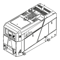
Provides a detailed dimension print of the welder, including trailer mounting locations and center of gravity.
Outlines Lincoln Electric's policy on providing advice and support for their products.