Do you have a question about the Lincoln Electric AIR VANTAGE 500 and is the answer not in the manual?
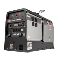
| Max Output | 500 Amps |
|---|---|
| Engine Power | 24.8 HP |
| Fuel Type | Diesel |
| Duty Cycle | 100% |
| Generator Output | 120/240V AC |
| Processes | Stick, TIG, MIG, Flux-Cored |
| Type | Engine Driven Welder/Generator |
| Rated Output | 500A/40V/100% |
Warnings about diesel engine exhaust constituents known to cause cancer, birth defects, or reproductive harm.
Precautions against electric shock, emphasizing insulation and dry gloves.
Warnings about breathing hazardous fumes and gases produced during welding.
Precautions to prevent fires and explosions from welding sparks and compressed gases.
Safety measures for handling compressed gas cylinders to prevent explosions.
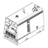
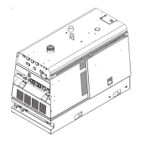
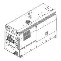
Detailed technical data for the AIR VANTAGE® 500 (AU) welder.
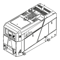
Guidelines for placing the welder to ensure proper airflow and exhaust venting.
Instructions for safely lifting and moving the welding machine.
Steps for checking engine oil, coolant, fuel, and battery before operation.
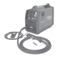
Guidance on connecting welding terminals and output cables.
Instructions for connecting remote controls and wire feeders.
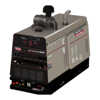
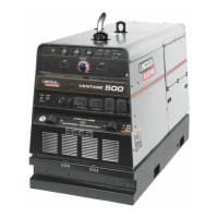
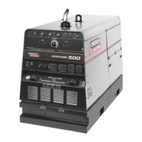
Overview of the AIR VANTAGE® 500 (AU) diesel engine welder's features.
Explanation of the switches and gauges for engine operation and monitoring.
Details on adjusting output, mode selection, and arc control for welding.
How to use Stick, CC-Stick, and Touch Start TIG welding modes.
Procedures for CV wire welding and arc gouging operations.
Essential safety rules for performing maintenance tasks on the equipment.
Daily and weekly checks for engine, compressor, and fuel systems.
Instructions for inspecting, cleaning, and replacing the engine air filter.
Guidelines for safely handling, connecting, and charging the battery.
Steps for diagnosing and resolving machine malfunctions using the guide.
Troubleshooting common problems related to engine cranking and starting.
Diagnosing issues like engine shutdown, rough running, or failure to stop.
Resolving problems with welding output, control, or auxiliary power.
Overall electrical schematic for the AIR VANTAGE® 500 (AU).
Diagram for connecting spool guns to the welder.
Diagram for connecting LN-7, K775, or K867 wire feeders.
Diagram for connecting the K930 TIG Module.
Diagram for connecting the LN-742 wire feeder.