B-2
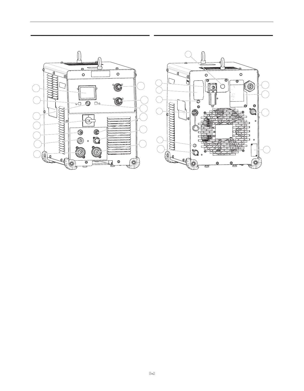
FIGURE B.1
1. LCD Display: Shows available modes and real time
parameters and system errors.
2. Home Button: Allows the user to return to the Home Screen
3. Menu Control Knob/Button: Used to navigate and select items
on the display.
4. On/Off Switch: Turns the input power to the machine ON/OFF.
5. Shield Gas Outlet: Connect a gas hose from here to the shield
gas inlet on the torch.
6. Nozzle Lead Connection: Connect a #6 AWG cable from here
to pilot connection in FlexStart
®
console.
7. Work Lead Connection: Connect a 1/0 AWG cable from here to
cutting table.
8. Electrode Lead Connection: Connect a 1/0 AWG cable from
here to electrode connection in the FlexStart
®
console.
9. ArcLink Connector (5 Pin): Provides power and commu-
nication to the FlexStart
®
console.
10. Plasma Gas Outlet: Connect gas hose from here to 2-Gang
plasma gas inlet.
11. Purge: Allows the user to enable airflow from the machine for
both plasma and shielding gas.
12. Shield Gas Regulator: Allows the regulation of the shield
air/gas pressure.
13. Plasma Gas Regulator: Allows the regulation of the plasma
air/gas pressure.
FIGURE B.2
14. Shielding Gas Inlet (optional): Allows ability for independent
air/gas to be connected for shield .
15. Plasma Gas Inlet: Compressed air or gas connection.
16. 115V/10A Auxiliary Power Receptacle.
17. 10 Amp Circuit Breaker (CB-2): Protects the 115V Auxiliary
Power Receptacle.
18. Ethernet Connector (RJ-45): Used for ArcLink® XT commu-
nication.
19. 10 Amp Circuit Breaker (CB-2): Protects the 40V ArcLink
Power Supply
20. ArcLink Connector (5 Pin): Provides power and commu-
nication to the FLEXCOOL cooler.
21. Analog Terminal Strip (optional): Provides additional input
controls for corner current reduction, hold, and remote poten-
tiometer control.
22. 14-Pin CNC Interface: Allows access to Arc Start Trigger, Arc
Initiated contact, raw or divided voltage Arc Voltage, and
Forced Mark.
23. Reconnect Panel Access: Allows the unit to be configured for
380/400/415, 460, or 575 VAC input.
24. Input Cord Strain Relief: Used to connect the unit to input
power.
1
2
3
4
5
6
7
13
12
11
10
9
8
14
15
16
17
18
19
20
21
22
23
24
FlexCut
®
200 CE
OPERATION
CASE FRONT CONTROLS CASE BACK CONTROLS