Do you have a question about the Lincoln Electric LN-25 SVM179-B and is the answer not in the manual?
| Input Frequency | 50/60 Hz |
|---|---|
| Processes | MIG, Flux-Cored |
| Wire Feed Speed Range | 50-700 ipm (1.3-17.7 m/min) |
| Drive Roll | 4-Roll |
| Wire Feed Motor Type | Permanent Magnet |
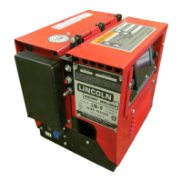
| Type | Portable Wire Feeder |
| Wire Size Range | 0.023-0.120 in (0.6-3.0 mm) |
Warnings specific to California regarding hazardous substances in engine exhaust.
Safety precautions for operating equipment powered by an engine.
Information on potential hazards of EMF fields from welding operations.
Hazards associated with welding fumes and gases and necessary ventilation.
Dangers of arc rays and protective measures for eyes and skin.
Precautions for handling compressed gas cylinders to prevent explosions.
Safety guidelines for operating electrically powered welding equipment.
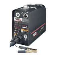
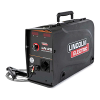
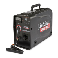
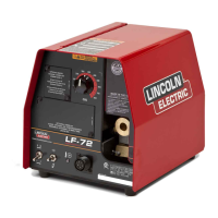
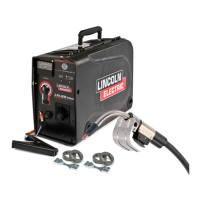
Key technical details and parameters of the LN-25™ PRO wire feeder.
Crucial safety guidelines to follow during installation and operation.
Guidance on optimal placement for the wire feeder.
Measures to prevent interference with radio-controlled equipment.
Recommendations for appropriate weld cable sizing based on current and duty cycle.
Instructions for connecting the shielding gas supply.
Information on configuring the wire drive system.
Procedure for replacing the gun receiver bushing.
Instructions for loading wire spools onto the feeder.
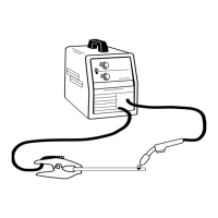
Steps for connecting the welding gun to the wire feeder.
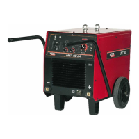
Diagrams for connecting to CV power sources with specific connector types.
Diagrams for connecting to CV power sources without Remote/Local switch.
Important safety rules and explanation of symbols used in the manual.
An overview of the LN-25™ PRO's design and capabilities.
How to set wire feed speed when using CV power sources.
A table providing wire speed settings based on arc voltage for CC operation.
Importance and connection of the work sense lead for motor operation.
Explanation of the thermal LED and automatic motor shutdown for overload protection.
Function of the polarity LED to indicate positive or negative polarity connection.
How to use the speed range switch for precise low-speed settings.
Functionality of the 2-step and trigger interlock switch for gun trigger operation.
How the CV/CC switch determines wire feed speed control method.
Using the cold feed button for threading electrode without power or gas.
Function and range of the preflow timer for gas purging and arc start.
Control of power source output after wire feed stops, prevents sticking.
Function and range of the postflow timer to protect the weld as it cools.
Function of the gas purge button for setting gas flow.
How the flow meter ball indicates shielding gas flow rate.
Valve used to adjust the shielding gas flow rate indicated by the meter.
Connection point for the shielding gas supply.
Connection for the electrode lead.
Ports for connecting a water-cooled gun system.
How the flowmeter indicates and allows adjustment of shielding gas flow rate.
Steps and indicators to observe during the machine's power-up sequence.
Equipment pre-installed on the wire feeder.
Different kits for drive rolls and wire guides for various wire types.
Accessory for a plastic case with pre-assembled components.
Power cable accessory for pulse welding.
Power cable accessory for pulse or STT™ welding.
Package including ground clamp and cables.
Power cable with specific connector types.
Power cable with lug connectors.
Kit for connecting power sources to turn weld terminals ON.
Kit providing adjustable preflow, postflow, and burnback.
Various bushings for connecting different welding guns.
Adapters for mounting different sizes of wire spools.
Kit for water-cooled gun models.
Gas regulator accessory with adapters.
Safety guidelines specifically for maintenance procedures.
Regular maintenance tasks for cables and terminals.
Periodic tasks like cleaning drive rolls and vacuuming the feeder.
Information on calibration status for voltmeter and flow meter.
Procedure to verify the accuracy of the analog voltmeter.
Procedure to verify the accuracy of the gas flow meter.
An overview of the LN-25™ PRO's design and capabilities.
How the unit receives and processes input power.
Explanation of the gun trigger's function and operation modes.
How the feeder monitors and controls motor speed and wire feed.
Description of optional features like timer kits and digital displays.
Instructions on how to effectively use the troubleshooting guide.
Steps for diagnosing and troubleshooting issues related to PC boards.
A table listing problems, possible causes, and recommended actions.
Steps to resolve inconsistent or failed wire feeding issues.
Troubleshooting steps when wire speed is incorrect or unresponsive.
Diagnosing issues where wire speed cannot be adjusted.
Troubleshooting slow wire feeding when the trigger is activated.
Diagnosing and fixing poor arc starts and bead quality issues.
Checks for verifying correct operation of key components after repair.
Wiring diagram for specific model codes.
Wiring diagram for specific model codes.
Wiring diagram for specific model codes.
Wiring diagram for specific model codes.