Do you have a question about the Lincoln Electric Power Feed 84 and is the answer not in the manual?
Details input voltage and current specifications for the equipment.
Specifies rated output values at 40°C, including duty cycle and input amperes.
Outlines the gearing, wire feed speed range, and compatible wire sizes.
Lists physical dimensions and weight for various components.
Provides operational and storage temperature ranges for the equipment.
Table detailing model numbers and their configurations for single wire drive feeders.
Table detailing model numbers and configurations for dual wire drive feeders.
Lists control box models and their interface/USB capabilities.
Table detailing ready pack wire drive feeder models and configurations.
Provides guidelines to minimize electromagnetic emissions from the machine.
Warns that Class A equipment is for industrial environments only.
Explains various warning symbols and their meanings for safe operation.
Details risks of electric shock and potential effects of EMF fields.
Warns about hazards from fumes, gases, arc rays, sparks, and hot materials.
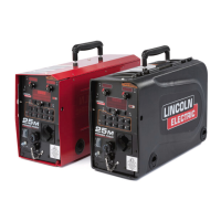
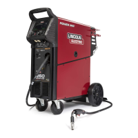
Describes the modular design and key features of the Power Feed 84 wire feeder.
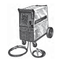
Advises on suitable placement and environmental considerations for the feeder.
Lists configurations where the user interface is mounted directly to the wire drive.
Lists configurations where the user interface is in a separate control box.
Explains how to convert between single and dual user interface configurations.
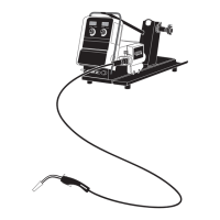
Describes the process of converting a bench feeder to a boom feeder.
Step-by-step instructions for detaching the user interface from the wire drive.
Details the process of installing a USB interface into the control box.
Provides instructions for installing new drive rolls and guides.
Explains how to adjust pressure for optimal wire feeding and avoid issues.
Instructions for installing gun adapters for Miller systems.
Steps for installing gun adapters, guide tubes, and connecting the gas hose.
Instructions on how to loosen and adjust the wire drive for desired position.
Explains how to change the pinion gear for speed or torque adjustment.
Step-by-step guide for connecting the shielding gas cylinder and regulator.
Instructions for installing the K590-6 water connection kit.
Instructions for loading spools onto the wire stand and retaining collar.
Details coaxial welding cable construction and usage for specific waveforms.
Instructions for placing the spindle on different wire reel stands.
Provides recommendations for coaxial cable sizes based on current and length.
Recommends standard cable sizes for different currents, duty cycles, and lengths.
Mentions how to select negative polarity welding via the setup menu.
Advises on managing arc blow and interference when using multiple arcs.
Describes available ArcLink control cable types for different environments.
Details pin functions for trigger and ArcLink connectors.
Describes power up sequence and provides a key to graphic symbols.
Identifies and numbers the various components of the user interface.
Explains the use of the left display and knob for WFS or amperage adjustment.
Details how the right display and knob control voltage/trim based on the process.
Describes how 'Trim' controls arc length in pulse welding and its effect.
Instructions on how to view gas flow rate and type on the display.
Guides on how to select weld modes using the menu or search function.
Explains Arc Force and Pinch functions for arc characteristics.
Details Ultimarc and Arc Control for focusing the arc and pulse frequency.
Explains Peak Current, Background Current, and Tail Out for arc control.
How to select between 2-Step and 4-Step trigger types.
Explains basic 2-step trigger operation with Start and Crater OFF.
Describes tailoring arc start and end with Start/Burnback for better quality.
Details customized 2-step trigger with start, crater, and burnback functions.
Discusses how trigger response depends on settings like START/CRATER/UPSLOPE.
Explains 4-step trigger with interlock for comfort during long welds.
Details 4-step trigger with manual control of start, crater, and burnback functions.
Explains when and how to select the spot trigger and its conditions.
Discusses trigger response based on timing and START/CRATER settings.
Lists available start options like Preflow, Run-in WFS, Start Time, WFS, and Volts.
Details end options like Spot Timer, Crater Time, Burnback Time, and Postflow Time.
Explains how to select between single or dual wire drives and use Cold Feed.
How to activate gas purge and use the gouging kit.
Explains how procedure memory is used during welding vs. user memory.
How limits constrain welding parameters and prevent exceeding values.
Lists machine limits for parameters like Wire Feed Speed, Voltage, and Trim.
How to enable/disable limits for specific memories using the memory button.
Instructions for loading and saving memories using a USB device.
How to exit the setup menu.
Settings for WFS units and the value shown during welding.
Choosing display info and enabling memory recall via trigger.
Options for remotely selecting procedures (External Switch, Quick Trigger, Integral Trig Proc).
Procedure for adjusting wire feed speed calibration for push-pull guns.
Controls for TIG gas solenoid and bypassing the crater sequence.
Setting how the potentiometer on the push-pull torch behaves.
Options for selecting the type of analog remote control used.
Selecting wire drive gear ratio and forward direction.
Sets time to shut off output if arc isn't established or is lost.
Instructions for loading and saving memories using a USB device.
Allows adjustment of the wire drive roll speed from -5% to +5%.
Settings for gas flow units and forcing voltage sensing.
Selecting electrode polarity and viewing voltage sense lead.
Settings for wire retract and overriding UI lockouts.
Enabling test modes and accessing diagnostic options for troubleshooting.
Viewing system logs and version information for software and hardware.
Checking IP address, power source protocol, and viewing lockout parameters.
Controls for memory overwriting and disabling memory buttons.
Locking mode select panel options and requiring passcode for setup menu.
Setting UI passcode and resetting all memories to default.
Settings for available USB options and the USB prompt.
Turns the USB-Key lock on or off for the feeder.
Instructions for installing and using the gouging kit.
Safety warnings for performing maintenance or repair operations.
Steps for calibrating WFS and performing routine maintenance checks.
Outlines Lincoln Electric's policy regarding customer advice and product responsibility.
Guidance on proper disposal of electrical equipment according to European directives.
Information on finding spare parts and authorized service facilities.
Electrical schematic for the single wire drive unit.
Electrical schematic for the dual wire drive unit (Sheet 1 of 2).
Electrical schematic for the dual wire drive unit (Sheet 2 of 2).
Electrical schematic for the control box with USB functionality.
Lists various drive roll and wire guide kits for different wire types.
Details different gun adapter kits and their compatibility.
Lists control cable options for connecting user interface and wire drive.
Accessories for conduit, wire straightening, and water connections.
Accessories including a digital meter, lift bail, and mounting brackets.
Accessories for wire reel stands and enclosures.
Accessories for gas filtering, flow sensing, and conduit inlet bushing.
Lists standard accessories included with the Power Feed 84.
| Brand | Lincoln Electric |
|---|---|
| Model | Power Feed 84 |
| Category | Welding System |
| Language | English |