EasyManua.ls Logo

Lincoln Electric POWER FEED IM584-D User Manual

Lincoln Electric POWER FEED IM584-D
68 pages
To Next Page IconTo Next Page
Page #1 background imageLoading...
Page #1 background image
Power Feed 10 Wire Drive & Control Box
Boom Mount or Bench Model
OPERATOR’S MANUAL
IM584-D
August, 2007
Safety Depends on You
Lincoln arc welding and cutting
equipment is designed and built
with safety in mind. However, your
overall safety can be increased by
proper installation ... and thought-
ful operation on your part. DO
NOT INSTALL, OPERATE OR
REPAIR THIS EQUIPMENT
WITHOUT READING THIS
MANUAL AND THE SAFETY
PRECAUTIONS CONTAINED
THROUGHOUT. And, most
importantly, think before you act
and be careful.
For use with:
Power Feed 10 Control Box - Boom Mount Code 10436, 10615
Power Feed 10 Wire Drive - Boom Mount Code 10437,10616, 10782
Power Feed 10 Boom Package Code 10435, 10612 (Generic), 10493, 10613 (12’ Zipline), 10494, 10614 (16’ Zipline),
10779 (Generic), 10767, 10780 (12’ Zipline), 10768, 10781 (16’ Zipline)
Power Feed 10 Bench Model Code 10438, 10617, 10760,10783
• Sales and Service through Subsidiaries and Distributors Worldwide •
Cleveland, Ohio 44117-1199 U.S.A. TEL: 216.481.8100 FAX: 216.486.1751 WEB SITE: www.lincolnelectric.com
• World's Leader in Welding and Cutting Products •
Copyright © 2007 Lincoln Global Inc.
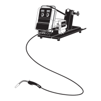
Table of Contents

Questions and Answers:

Lincoln Electric POWER FEED IM584-D Specifications

General IconGeneral
BrandLincoln Electric
ModelPOWER FEED IM584-D
CategoryWelding System
LanguageEnglish

Summary

General Safety Precautions

Welding Hazard Safety

Electric Shock Prevention

Essential precautions to avoid electrical shock during welding operations.

Arc Ray Protection

How to protect eyes and skin from harmful arc rays.

Operational Safety Hazards

Fire and Explosion Prevention

Measures to prevent fires and explosions caused by welding sparks.

Cylinder Safety Precautions

Precautions for handling compressed gas cylinders to prevent explosions.

Technical Specifications

Installation and Mounting Procedures

Installation Safety Precautions

Critical safety steps before performing installation tasks.

Wire Drive Configuration

Wire Drive Gear Ratio

How to select and change the wire drive gear ratio for speed and torque.

DIP Switch Setup Procedures

Control Box DIP Switch Settings

Configuration of DIP switches on the control box motherboard for various functions.

Wire Drive DIP Switch Settings

Wire Drive Control Board Settings

Configuration of DIP switches on the wire drive PC board for settings like polarity and ratio.

Drive Roll and Gun Installation

Installing Drive Rolls and Guides

Step-by-step procedure for installing drive rolls and wire guides.

Control Box Operation Overview

Control Box Panels Overview

Explanation of the functions of the Control/Display panel and other panels.

Control Box Panel Functions

Large Optional Panel Operations

Setup Controls Parameter Definitions

Parameter Definitions

Explanation of parameters like Preflow, Run In, Arc Control, Burnback, Postflow.

Control Box Adjustments and Limits

Setting Operating Limits

How to set upper and lower limits for WFS/Amps and Volts/Trim.

Wire Drive Operation

Wire Reel Loading Procedures

Electrode and Drive Adjustments

Welding and Wire Management

Making a Weld

Step-by-step guide for performing a weld using the system.

Component Status Lights

Status Light States

Interpretation of LED status lights for diagnosing system conditions.

MX2 Panel Operation

MSP2/MS/STT Panel Operation

Dual Procedure / Memory Panel

K1542-9 Dual Procedure/Memory Panel Installation

Steps to install and use the K1542-9 Dual Procedure/Memory Panel.

Linc Net Receptacle Kits

Maintenance Procedures

Troubleshooting Guide

How to Use the Troubleshooting Guide

Instructions on how to use the troubleshooting steps.

Wire Feeding Problem Troubleshooting

Rough Wire Feeding Issues

Diagnosing and resolving problems with rough or stopped wire feeding.

Arc and Bead Quality Troubleshooting

Unit Operation Troubleshooting

Control and Feed Troubleshooting

Speed and Switch Troubleshooting

Display and Procedure Troubleshooting

Error Code Troubleshooting

Error Code Troubleshooting

Explaining and resolving error codes displayed by the system.

Wiring Diagrams

Control Box Wiring Diagram

Schematic showing electrical connections for the Power Feed 10 control box.

Wire Drive Wiring Diagram

Power Feed 10 Wire Drive Wiring

Schematic illustrating the electrical connections of the Power Feed 10 wire drive.

Related product manuals