Do you have a question about the Lincoln Electric POWER WAVE455M and is the answer not in the manual?
Warnings related to California Proposition 65 regarding engine exhaust.
Safety guidelines for operating engine-powered equipment.
Precautions regarding exposure to electric and magnetic fields during welding.
Warnings and precautions to prevent electric shock during welding operations.
Safety measures to protect against burns from arc rays.
Safety guidelines for dealing with hazardous fumes and gases produced during welding.
Precautions to prevent fires and explosions caused by welding sparks and hot materials.
Safety measures for handling compressed gas cylinders to prevent explosions.
Guidelines for the safe installation and grounding of electrically powered equipment.
General safety advice for arc welding operations.
Specific safety precautions for transformer and rectifier welding machines.
Detailed technical specifications for the POWER WAVE® 455M.
Guidelines for choosing an appropriate and safe location for the equipment.
Instructions for safely lifting the welding machine.
Instructions for safely stacking the welding machine.
Safety guidelines to follow before starting the installation process.
Requirements and procedures for properly grounding the welding machine frame.
Precautions regarding interference with radio-controlled machinery.
Instructions for connecting the primary power supply to the machine.
Guidelines for selecting appropriate input fuses and supply wire sizes.
Procedure for changing the input voltage configuration of the machine.
Instructions for correctly connecting electrode and work cables.
How cable inductance affects pulse welding performance.
Instructions for setting negative electrode polarity when required.
Information on using voltage sensing leads for better arc performance.
How to enable and configure electrode voltage sensing.
Procedure for enabling and configuring work voltage sensing.
How to connect the Power Wave to semi-automatic wire feeders.
Overview of the digital communication system (ArcLink) used by the products.
Instructions on configuring the welding system for different setups.
Diagram showing single head feeder system setup.
Diagram showing dual head feeder system setup.
Diagram showing single head boom feeder system setup.
Setup for alternate hard automatic welding applications.
Setup for combination hard automation applications.
Configuration for dual head boom feeder systems.
Guidelines for using multiple Power Wave units simultaneously.
Information on recommended control cables and their specifications.
Guidelines for placing sense and work leads in multiple arc systems.
Details on input/output receptacle pin assignments and functions.
How to access and configure DIP switches on the control board.
Information on the water flow sensor and its importance.
Safety guidelines to follow before operating the machine.
Explanation of graphic symbols used in the manual and on the machine.
Glossary of welding terms used in the manual.
Overview of the Power Wave® semi-automatic welding system.
Information on compatible welding processes and required equipment.
Key limitations and warnings associated with the Power Wave® system.
Description of the controls and indicators located on the front of the machine.
Diagram illustrating the layout of controls on the machine's front panel.
Standard procedures for operating the Power Wave® for welding.
Procedures for limited operational conditions, like short/long electrode stick-outs.
Step-by-step guide for performing a weld with the system.
How to adjust welding parameters like WFS and voltage.
How to select different welding modes available on the machine.
Adjusting arc characteristics for different welding conditions.
Explanation of constant voltage welding modes (synergic and non-synergic).
Details on setting up and performing pulse welding procedures.
List of optional equipment available for the Power Wave system.
Options that are factory installed on the machine.
Options that can be installed in the field after purchase.
Information on other Lincoln equipment compatible with the Power Wave.
Safety guidelines to follow before performing maintenance.
Recommended periodic cleaning and basic maintenance tasks.
Guidelines for periodic checks and calibration.
Information on output voltage and current calibration procedures.
Instructions on how to effectively use the troubleshooting section of the manual.
Guidance on interpreting the status LED for diagnosing system problems.
A list of error codes and their corresponding indications for troubleshooting.
Troubleshooting steps for evident physical or electrical damage.
Steps to diagnose and resolve input fuse blowing or breaker tripping issues.
Troubleshooting steps when the machine does not power on.
Diagnosing issues when the thermal overload indicator is on.
Steps to troubleshoot when the machine fails to produce output.
Diagnosing and resolving issues causing limited output or "noodle welds".
Troubleshooting steps when the machine does not achieve full output.
Diagnosing issues with the auxiliary receptacle not providing voltage.
Steps to address overall degradation in welding performance.
Troubleshooting excessive length and erratic behavior of the welding arc.
Electrical wiring diagram for Power Wave 455M with code 10942.
Electrical wiring diagram for various Power Wave 455M codes.
Electrical wiring diagram for Power Wave 455M with specific codes.
Diagram showing a basic semi-automatic system connection.
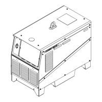
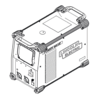
Physical dimensions and layout of the Power Wave® 455M machine.
| Output Current Range | 5-455 A |
|---|---|
| Output Voltage Range | 10-40 V |
| Duty Cycle | 100% at 455 A |
| Efficiency | 85% |
| Input Phase | 3 |
| Rated Output | 455 A at 32 V |
| Processes | MIG, TIG, Stick |
| Wire Feed Speed Range | 50-800 ipm (1.3-20.3 m/min) |