EasyManua.ls Logo

Lincoln Electric POWER WAVE SVM173-A User Manual

Lincoln Electric POWER WAVE SVM173-A
165 pages
To Next Page IconTo Next Page
Page #1 background imageLoading...
Page #1 background image
SVM173-A
April, 2007
Safety Depends on You
Lincoln arc welding and cutting
equipment is designed and built
with safety in mind. However,
your overall safety can be in-
creased by proper installation . . .
and thoughtful operation on
your part. DO NOT INSTALL,
OPERATE OR REPAIR THIS
EQUIPMENT WITHOUT
READING THIS MANUAL AND
THE SAFETY PRECAUTIONS
CONTAINED THROUGHOUT.
And, most importantly, think
before you act and be careful.
SERVICE MANUAL
For use with machines having Code Numbers: 10942 10957
11007 11008
11057 11153
11152
POWER WAVE 455M/STT
TM
Return to Master TOC Return to Master TOC Return to Master TOC Return to Master TOC
View Safety Info View Safety Info View Safety Info View Safety Info
POWERWAVE 455
I ON
O OFF
POWERWAVE 455
• Sales and Service through Subsidiaries and Distributors Worldwide •
Cleveland, Ohio 44117-1199 U.S.A. TEL: 1-888-935-3877 WEB SITE: www.lincolnelectric.com
• World's Leader in Welding and Cutting Products •
Copyright © Lincoln Global Inc.

Table of Contents

Question and Answer IconNeed help?

Do you have a question about the Lincoln Electric POWER WAVE SVM173-A and is the answer not in the manual?

Lincoln Electric POWER WAVE SVM173-A Specifications

General IconGeneral
BrandLincoln Electric
ModelPOWER WAVE SVM173-A
CategoryWelding System
LanguageEnglish

Summary

Safety Depends on You

Machine Code Identification

Lists code numbers for compatible machines.

Lincoln Electric Service Manual

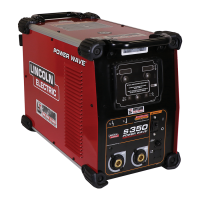
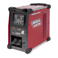
Indicates this is the official service manual from Lincoln Electric.

General Safety Precautions

California Proposition 65 Warnings

Specific warnings regarding chemicals known to cause cancer and birth defects.

Engine Powered Equipment Safety

Safety guidelines for operating and maintaining engine-powered equipment.

Electric and Magnetic Fields Hazards

Information on potential dangers of EMF fields, especially for pacemaker wearers.

Welding Hazards and Protection

Electric Shock Hazards

Precautions to avoid severe or fatal electrical shock from welding equipment.

Arc Ray Hazards

Guidance on protecting eyes and skin from arc rays and spatter.

Fumes and Gases Hazards

Safety measures for avoiding inhalation of hazardous welding fumes and gases.

Fire and Explosion Safety

Welding Spark Hazards

Precautions to prevent fires and explosions caused by welding sparks.

Cylinder Explosion Hazards

Safety guidelines for handling compressed gas cylinders to prevent explosion.

Electrical Equipment Safety

Safety considerations for electrically powered equipment during installation.

French Safety Precautions

Arc Welding Safety

General safety precautions for arc welding in French.

Transformer and Rectifier Welder Safety

Specific safety advice for transformer and rectifier welding machines in French.

Technical Specifications

Output Specifications

Details on output current, voltage, and duty cycle ratings.

Input Wire and Fuse Requirements

Recommended input wire gauge and fuse/breaker sizes for safe operation.

Installation Safety and Location

Electrical Safety During Installation

Critical electrical safety warnings before starting installation procedures.

Site Selection and Handling

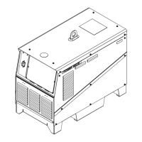
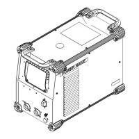
Guidance on choosing a suitable location and proper lifting/stacking methods.

Grounding and HF Protection

Instructions for machine grounding and high frequency protection setup.

Input Power Connection

Electrical Connection Diagrams

Diagrams illustrating proper input power connections for various voltages.

Fuse and Wire Considerations

Guidelines for selecting appropriate input fuses and supply wires.

Welding Cable and Polarity Setup

Electrode and Work Cable Connections

Proper procedures for connecting electrode and work cables for optimal performance.

Voltage Sensing System

Voltage Sensing Explanation

Details on how voltage sensing improves arc condition accuracy and performance.

System Connectivity and Settings

Work and Electrode Voltage Sensing

Configuration of voltage sensing leads for different welding processes.

Wire Feeder Interconnections

Instructions for connecting the Power Wave to wire feeders.

DIP Switch Configuration

Control Board DIP Switch Settings

Guide to configuring the Control Board using DIP switches.

Operation Safety Precautions

Electric Shock During Operation

Warnings about energized parts and handling the machine during operation.

Fumes, Gases, Sparks, and Arc Ray Hazards

Safety measures against fumes, gases, sparks, and arc rays during operation.

General Machine Description

Design Features and Advantages

Overview of key features and benefits of the Power Wave welding system.

Recommended Setup and Limitations

Recommended Processes and Equipment

Guidance on suitable welding processes and required equipment.

Duty Cycle Considerations

Explanation of duty cycle ratings and their impact on operation.

Case Front Controls Overview

Power Switch and Status Light

Description of the main power switch and system status indicator light.

Welding Mode Descriptions

Constant Voltage (CV) Welding

Explanation of how Constant Voltage welding mode functions.

Welding Mode Descriptions (Continued)

Pulse Welding Parameters

Details on adjusting parameters like 'trim' for pulse welding arc length.

Welding Mode Descriptions (Continued)

STT Welding Controls

Explanation of STT mode adjustments for tailout and peak current.

Maintenance Safety and Procedures

Routine and Periodic Maintenance Tasks

Guidelines for daily checks and periodic internal cleaning procedures.

Theory of Operation Overview

Block Logic Diagram

High-level block diagram illustrating the machine's functional logic.

General Machine Description (Theory)

Machine Processes and Ratings

Overview of supported processes and the machine's output ratings.

Input Voltage and Precharge Theory

Input Voltage and Precharge Sequence

Explanation of the machine's power-up sequence and voltage handling.

Transformer and Switch Board Theory

Switch Boards and Main Transformer Function

Theory of operation for switch boards and the main transformer.

Power Supply Board Theory

DC Bus, Power, and Gateway Board Operation

Explanation of the functions of the DC Bus, Power, and Gateway boards.

System Communication Theory

Power Wave Communications Diagram

Diagram illustrating communication flow between system components.

Control Board Functionality

Control Board Operation and Monitoring

How the Control Board manages output and monitors system parameters.

Protective Circuits and Overloads

Thermal and Protective Circuits

Explanation of thermal protection and other protective circuits.

Over Current and Voltage Protection

Details on over current, under voltage, and over voltage protection mechanisms.

IGBT Operation Theory

Insulated Gate Bipolar Transistor Basics

Explanation of how Insulated Gate Bipolar Transistors (IGBTs) function.

Pulse Width Modulation Theory

PWM for Minimum and Maximum Output

How pulse width modulation controls machine output power.

Troubleshooting Guide Introduction

How to Use the Troubleshooting Guide

Step-by-step instructions on using the troubleshooting guide effectively.

PC Board Troubleshooting Procedures

PC Board Static Electricity Precautions

Guidance on handling PC boards safely to prevent static discharge damage.

PC Board Replacement and Verification

Procedure for testing and verifying replacement of suspect PC boards.

Troubleshooting Output Problems

Input Fuses or Breakers Tripping

Troubleshooting steps for repeated input fuse or circuit breaker trips.

Troubleshooting Output Problems (Continued)

Machine Dead or No Output

Diagnosing issues when the machine shows no power or output.

Troubleshooting Output Problems (Continued)

No Welding Output, Contactor Not Activating

Troubleshooting steps when the main contactor is not activating.

Machine Overheating Issues

Diagnosing and resolving frequent machine overheating problems.

Troubleshooting Function Problems

Noodle Welding or Limited Output

Diagnosing 'noodle welding' or low output issues, often due to current limits.

Troubleshooting Function Problems (Continued)

STT Process Inconsistency

Troubleshooting inconsistent arc and high spatter in STT mode.

Input Filter Capacitor Discharge Procedure

Procedure Description and Materials

Overview and required materials for safely discharging input filter capacitors.

Switch Board Testing

Switch Board Resistance Test

Procedure for testing switch boards using resistance measurements.

Input Rectifier Testing

Input Rectifier Diode Test

Method for testing input rectifier diodes for shorts or open circuits.

Input Contactor Testing

Input Contactor Coil and Contact Test

Procedure to test the functionality of the input contactor coil and contacts.

DC Bus Power Supply PC Board Test

DC Bus Power Supply Voltage Checks

Testing the DC Bus Power Supply PC Board for proper input and output voltages.

Power Board Testing

Power Board Voltage Checks

Procedure to verify Power Board receives correct voltages and produces correct DC voltages.

Input Board Testing

Input Board Voltage Checks

Testing the Input Board for sending and regulating correct DC voltages.

STT Chopper Board Testing

STT Chopper Board Resistance and Voltage Tests

Procedure to determine if the STT Chopper Board receives necessary voltages.

Power Wave Current Transducer Test

Current Transducer Supply and Feedback Voltage Tests

Testing the Power Wave current transducer and associated wiring for correct function.

STT Current Transducer Test

STT Current Transducer Supply and Feedback Voltage Tests

Testing the STT current transducer and associated wiring for correct function.

Output Rectifier Test

Output Rectifier Resistance Test

Procedure to determine if any output rectifiers are shorted.

Auxiliary Transformer No. 1 Test

Auxiliary Transformer No. 1 Voltage Checks

Testing primary voltage input and secondary voltage output of Auxiliary Transformer No. 1.

Auxiliary Transformer No. 2 Test

Auxiliary Transformer No. 2 Voltage Checks

Testing primary voltage input and secondary voltage output of Auxiliary Transformer No. 2.

Input Rectifier Removal and Replacement

Input Rectifier Removal Procedure

Step-by-step guide for safely removing the input rectifier module.

Input Rectifier Replacement Procedure

Steps for installing a new input rectifier module, including thermal compound application.

Input Contactor Removal and Replacement

Input Contactor Removal Procedure

Step-by-step guide for safely removing the input contactor.

Input Contactor Replacement Procedure

Steps for installing a new input contactor and reconnecting leads.

Auxiliary Transformer No. 1 Removal and Replacement

Auxiliary Transformer No. 1 Removal Procedure

Step-by-step guide for safely removing Auxiliary Transformer No. 1.

Auxiliary Transformer No. 1 Removal and Replacement (Continued)

Auxiliary Transformer No. 1 Replacement Procedure

Steps for installing Auxiliary Transformer No. 1 and reconnecting leads.

Auxiliary Transformer No. 2 Removal and Replacement

Auxiliary Transformer No. 2 Removal Procedure

Step-by-step guide for safely removing Auxiliary Transformer No. 2.

Auxiliary Transformer No. 2 Removal and Replacement (Continued)

Auxiliary Transformer No. 2 Replacement Procedure

Steps for installing Auxiliary Transformer No. 2 and reconnecting leads.

PC Board Removal and Replacement

Control, Feed Head, or Voltage Sense PC Board Procedures

Procedures for removing and replacing Control, Feed Head, or Voltage Sense PC Boards.

Gateway PC Board Removal and Replacement

Gateway PC Board Removal Procedure

Steps for safely removing the Gateway PC Board.

STT Current Transducer Removal and Replacement

STT Current Transducer Removal Procedure

Steps for safely removing the STT Current Transducer.

Power Wave Current Transducer Removal and Replacement

Power Wave Current Transducer Removal Procedure

Steps for safely removing the Power Wave Current Transducer.

Output Rectifier, STT Chopper Board, and Rectifier Module Removal and Replacement

Rectifier Assembly Removal Procedure

Procedure for removing the output rectifier assembly.

Switch Board and Filter Capacitor Removal and Replacement

Switch Board and Filter Capacitor Removal Procedure

Steps for removing switch boards and filter capacitors.

Retest After Repair

Input Idle Amps and Watts

Specifications for input idle current and power consumption.

Electrical Diagrams

Wiring Diagram - Entire Machine - Code 10942 (G4212)

Wiring diagram for machine code 10942.

Electrical Diagrams (Continued)

Wiring Diagram - Entire Machine - Codes 10957 - 11311 (G4420)

Wiring diagram for machine codes 10957 through 11311.

Electrical Diagrams (Continued)

Schematic - Entire Machine - Code 10942 (G4211)

Schematic diagram for machine code 10942.

Electrical Diagrams (Continued)

Schematic - Entire Machine - Codes 10957 - 11311 Pg 1 Of 3 (G4421)

First page of the schematic for machine codes 10957-11311.

Electrical Diagrams (Continued)

Schematic - Entire Machine - Codes 10957 - 11311 Pg 2 Of 3 (G4421)

Second page of the schematic for machine codes 10957-11311.

Electrical Diagrams (Continued)

Schematic - Entire Machine - Codes 10957 - 11311 Pg 3 Of 3 (G4421)

Third page of the schematic for machine codes 10957-11311.

Electrical Diagrams (Continued)

Schematic - Chopper PC Bd - (STT Models Only) (L11340-2)

Schematic for the STT Chopper PC Board.

Electrical Diagrams (Continued)

PC Board Assembly - Chopper PC Bd - (STT Models Only) - (G3339-2)

PC board assembly diagram for the STT Chopper PC Board.

Electrical Diagrams (Continued)

Schematic - DeviceNet/Gateway PC Board (Robotic Model Only) Pg 1 Of 2 (G3821-2)

First page of the DeviceNet/Gateway PC Board schematic.

Electrical Diagrams (Continued)

Schematic - DeviceNet/Gateway PC Board (Robotic Model Only) Pg 2 Of 2 (G3821-2)

Second page of the DeviceNet/Gateway PC Board schematic.

Electrical Diagrams (Continued)

PC Board Assembly - DeviceNet/Gateway PC Board (Robotic Model Only) (L11046-2)

PC board assembly diagram for the DeviceNet/Gateway PC Board.

Electrical Diagrams (Continued)

Schematic - Control PC Board (All Codes) Pg 1 Of 4 (G3789-2)

First page of the Control PC Board schematic.

Electrical Diagrams (Continued)

Schematic - Control PC Board (All Codes) Pg 2 Of 4 (G3789-2)

Second page of the Control PC Board schematic.

Electrical Diagrams (Continued)

Schematic - Control PC Board (All Codes) Pg 3 Of 4 (G3789-2)

Third page of the Control PC Board schematic.

Electrical Diagrams (Continued)

Schematic - Control PC Board (All Codes) Pg 4 Of 4 (G3789-2)

Fourth page of the Control PC Board schematic.

Electrical Diagrams (Continued)

PC Board Assembly - Control PC Board (All Codes) (L11088-2)

PC board assembly diagram for the Control PC Board.

Electrical Diagrams (Continued)

Schematic - Digital Power Supply PC Board (All Codes) (G3631-3)

Schematic for the Digital Power Supply PC Board.

Electrical Diagrams (Continued)

PC Board Assembly - Digital Power Supply PC Board (All Codes) (G3632-3)

PC board assembly diagram for the Digital Power Supply PC Board.

Electrical Diagrams (Continued)

Electrical Diagrams (Continued)

Electrical Diagrams (Continued)

Electrical Diagrams (Continued)

PC Board Assembly - FeedHead PC Board (Robotic Model Only) (L11087-3)

PC board assembly diagram for the FeedHead PC Board.

Electrical Diagrams (Continued)

Schematic - Input PC Board (All Codes) (M19528-2)

Schematic for the Input PC Board.

Electrical Diagrams (Continued)

PC Board Assembly - Input PC Board (All Codes) (L11396-2)

PC board assembly diagram for the Input PC Board.

Electrical Diagrams (Continued)

Schematic - Switch PC Board (All Codes) (L11385-3)

Schematic for the Switch PC Board.

Electrical Diagrams (Continued)

PC Board Assembly - Switch PC Board (All Codes) (G3734-3)

PC board assembly diagram for the Switch PC Board.

Electrical Diagrams (Continued)

Electrical Diagrams (Continued)

PC Board Assembly - Voltage Sense PC Board (Robotic Model Only) (M19540-3)

PC board assembly diagram for the Voltage Sense PC Board.

Electrical Diagrams (Continued)

Schematic - 40 VDC Bus PC Board (All Codes) (M19330-2)

Schematic for the 40 VDC Bus PC Board.

Electrical Diagrams (Continued)

PC Board Assembly - 40 VDC Bus PC Board (All Codes) (L11078-2)

PC board assembly diagram for the 40 VDC Bus PC Board.

Related product manuals