Do you have a question about the Lincoln Electric RANGER 9 SVM 110-A and is the answer not in the manual?
| Brand | Lincoln Electric |
|---|---|
| Model | RANGER 9 SVM 110-A |
| Category | Welding System |
| Language | English |
Health warnings regarding engine exhaust contents.
General safety precautions for engine-powered operation.
Hazards and safety measures for EMF exposure.
Critical safety information to prevent electrocution.
Safety measures against arc rays and welding sparks.
Health risks and precautions for welding fumes/gases.
Safety guidelines for handling compressed gas cylinders.
Safety measures for electrical components and systems.
Essential safety guidelines before installation and operation.
Guidelines for proper machine placement and storage.
Safe practices for tilting, lifting, and high altitude use.
Pre-operation checks for engine oil and fuel.
Procedures for connecting power and grounding.
Proper selection, installation, and grounding of welding cables.
Setup for auxiliary power and circuit breaker functions.
Crucial safety rules for operating the equipment.
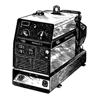
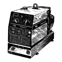
Overview of machine capabilities and design.
Constraints and recommended uses for the RANGER 9.
Explanation of all machine controls and their functions.
Detailed breakdown of welder and generator controls.
How to select welding output range and polarity.
Choosing between remote or automatic contactor control.
Details of power receptacles and amphenol connectors.
Controls related to the gasoline engine operation.
Using choke, idler, and start/stop controls for engine.
Using engine meters and safe operation guidelines.
Step-by-step guide for starting and operating the engine.
Instructions for performing various welding processes.
Instructions for performing stick welding.
Instructions for performing TIG welding.
Instructions for performing wire feed welding.
Overview of welding processes and settings.
Guidelines for using the generator's auxiliary power.
General information on generator output.
Guidelines for motor use and combined loads.
Optional equipment for moving the machine.
Various optional items like brackets and covers.
Accessories for TIG and wire feed welding.
Specific instructions for connecting wire feeders.
Specific connection instructions for LN-25 feeders.
Connection instructions for other Lincoln feeders.
Instructions for connecting a spool gun.
Essential safety guidelines for performing maintenance.
Regular maintenance tasks for the machine.
Engine maintenance intervals and oil change guide.
Procedures for oil filter, fuel, and fuel filter maintenance.
Maintenance for air cleaner, plugs, and other engine parts.
Procedures for maintaining the battery system.
Cleaning, checking gravity, and electrolyte levels.
Safe battery charging and handling procedures.
Maintenance tasks for the welder and generator components.
Guidelines for machine storage, cleaning, and brush care.
Inspecting and maintaining generator brushes and slip rings.
Explanation of battery, starter, engine, rotor, stator, solenoid.
How field feedback, auxiliary, and wire feeder power are generated.
Function of weld winding, reactor, and range switch.
Operation of output bridge, choke, polarity switch, and terminals.
Instructions on navigating the troubleshooting process.
Procedures for diagnosing printed circuit board issues.
Steps to resolve common output problems.
Steps to resolve no output and no auxiliary power issues.
Troubleshooting when only weld output is missing.
Troubleshooting when only auxiliary power is missing.
Diagnosing and fixing low output issues.
Addressing problems with DC or AC welding output.
Resolving issues with Constant Voltage welding output.
Steps to resolve engine-related problems.
Diagnosing and fixing engine idle and speed problems.
Troubleshooting engine start failures and low power.
Diagnosing and fixing welding arc problems.
Identifying and fixing a cold welding arc.
Troubleshooting general machine functions.
Troubleshooting welder output control failures.
Diagnosing wire feeder and contactor problems.
Step-by-step procedures for testing components.
Testing rotor electrical properties.
Testing stator windings and charging system.
Testing output rectifier and capacitor bank.
Adjusting engine speed for optimal performance.
Instructions for removing and replacing major components.
Procedures for maintaining generator brushes and slip rings.
Replacing field capacitor and rectifier bridge.
Removing, replacing, and handling PC boards.
Removing and replacing the output rectifier bridge.
Removing and replacing the output capacitor bank.
Removing and replacing the output contactor.
Procedures for engine and rotor removal/replacement.
Steps for rotor removal and full reassembly.
Final verification steps after completing repairs.
Electrical schematic for Code 9975 models.
Electrical schematic for Code 9976 CSA models.
Schematic and layout of the control PC board.
Schematic and layout of the RF bypass PC board.
Physical dimensions and mounting hole information.
List of components on the control PC board.
List of components on the RF bypass PC board.