EasyManua.ls Logo

Lincoln 84852 - User Manual

Lincoln 84852
4 pages
Print Icon
To Next Page IconTo Next Page
Loading...
LINCOLN
Models 84852, 84853, 84855, 84856
1“AIR-POWERED DIAPHRAGM PUMP
Series “B”
OPERATING AND
SERVICE INSTRUCTIONS
HAZARD WARNING
POSSIBLE EXPLOSION
HAZARD can result if 1,1,1,
-Trichloroethane, Methylene
Chloride or other Halogenated
Hydrocarbon solvents are used
in pressurized fluid systems
having Aluminum or Galvanized
wetted parts.
Death, serious
bodily injury and/or property
damage could result. Consult
with the factory if you have
questions concerning Haloge-
nated Hydrocarbon solvents.
Do not use for pumping flam-
mable materials. Build up and
discharge of static electricity
may result in a fire and/or ex-
plosion causing personal injury
and loss to property.
Principle of Operation
The pump is powered by compressed
air which alternately pressurizes the
inner sides of the two diaphragm cham-
bers while simultaneously exhausting
OPERATING INSTRUCTIONS, SERVICE MANUAL
AND REPAIR PARTS LIST
the opposite inner chambers causing
the diaphragms, which are connected
by a shaft, to move endwise. Since air
pressure is applied over the entire sur-
face of the diaphragm which is forcing
liquid to be discharged by its other side,
the diaphragm is operating under a
balanced condition during the dis-
charge stroke. This allows the unit to be
operated at discharge heads over 200
feet (61 meters) of water head.
Alternate pressurizing and exhaust-
ing of the diaphragm chamber is per-
formed by an externally mounted, pilot-
operated, four way, spool type air distri-
bution valve. When the spool is at one
end of the valve body, inlet air pressure
is connected to one diaphragm cham-
ber and theother diaphragm chamber is
connected to the exhaust. When the
spool is moved to the opposite end of
the valve body, the porting of chambers
is reversed. The air distribution valve
spool is moved from one end position to
the other in the valve body by means of
an internal pilot valve which alternately
pressurizes the ends of the air distribu-
tion valve spool while simultaneously
exhausting the other ends. The pilot
valve is positively shifted at each end of
the diaphragm stroke by the diaphragm
plate’s coming in contact with the end of
the pilot valve spool and pushing it into
position for shifting of the air distribu-
tion valve. The chambers are mani-
folded together with a suction and dis-
charge check valve for each chamber to
maintain flow in one direction through
the pump.
INSTALLATION
PROCEDURES
Position the pump as close as possi-
ble to the source of the liquid to be
pumped. Avoid long or undersize suc-
tion lines and use the minimum number
of fittings.
For permanent installation involving
rigid piping, install short flexible sec-
tions of hose between the pump and
piping. This reduces strains and per-
mits easier removal of the pump for
service when required. At time of insta-
llation, inspect all external gasketed
fasteners for looseness caused by
gasket creep. Tighten loose fittings
securely to prevent leakage.
AIR SUPPLY
Do not connect the unit to an air
supply in excess of 125 PSI (8 61 bars).
Install a shutoff valve in the air supply
line to permit removal of the unit for
servicing. When connecting an air sup-
ply of rigid piping, mount a section of
flexible line to the pump to eliminate
piping strain. In permanent installa-
tions, an air line filter IS recommended.
The weight of the air supply line and
of the filter must be supported by
some means other than the air valve
cap. Failure to provide support may
result in damage to the pump. A
pressure regulating valve should be
installed to prevent pressure from
exceeding recommended limits.
OPERATION
Your pump has been tested prior to
shipment and is ready for use as received
It is completely self-priming and no ini-
tial filling with fluid is required.
If the unit is to be totally submerged,
the air exhaust must be piped above
liquid level to prevent the liquid and
foreign material from entering the air
distribution valve mechanism.
Open the inlet air valve at least one
turn to allow sufficient cycling rate for
the pump to prime (30 to 60 cycles per
minute). After pumping starts, adjust
the inlet air valve for the desired pump
ing capacity. When further opening of
the inlet air valve increases cycling rate
without increasing the flow rate, the
pump is being starved of liquid due to
suction limitations. Further opening of
the airinlet valve will waste compressed
air. Set the inlet air valve for lowest
cycling rate that does not decrease flow
rate for most efficient operation.
LINCOLN
Section
-
B5
Page
-
15D
FEB-95
FORM 402581
Question and Answer IconNeed help?

Do you have a question about the Lincoln 84852 and is the answer not in the manual?

Overview

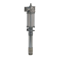
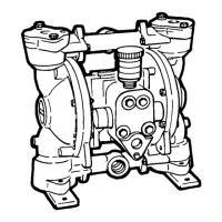
The Lincoln 1" Air-Powered Diaphragm Pump, Series "B" (Models 84852, 84853, 84855, 84856) is a robust device designed for transferring various fluids, operating on compressed air. Its primary function is to alternately pressurize the inner sides of two diaphragm chambers while simultaneously exhausting the opposite inner chambers. This action causes the diaphragms, which are connected by a shaft, to move endwise. A key design feature is that air pressure is applied over the entire surface of the diaphragm that is forcing liquid to be discharged. This creates a balanced condition during the discharge stroke, enabling the unit to operate at discharge heads exceeding 200 feet (61 meters) of water.

The pump's operation is controlled by an externally mounted, pilot-operated, four-way, spool-type air distribution valve. This valve shifts the air supply between the diaphragm chambers, connecting one to inlet air pressure and the other to exhaust. The spool is moved by an internal pilot valve, which is positively shifted at each end of the diaphragm stroke when the diaphragm plate contacts the pilot valve spool. The chambers are manifolded together with suction and discharge check valves for each chamber, ensuring unidirectional flow through the pump.

Important Technical Specifications:

The pump is designed to operate with an air supply not exceeding 125 PSI (8.61 bars). A pressure regulating valve is recommended to prevent exceeding these limits. The manual lists various repair kits available for different models, including:

  • 86252 Air End Repair Kit - All Models
  • 86244 Hytrel Wet End Repair Kit - Models 84852 & 84856
  • 86245 Teflon Wet End Repair Kit - Model 84853
  • 86237 Buna-N Wet End Repair Kit - Model 84855

The service parts list details components such as the spool valve body, sleeve and spool set, O-rings, capscrews, washers, nuts, diaphragm chambers, plungers, bumpers, bearings, seals, ball retainers, check valves, and manifolds, with specific part numbers for each model and material types like Fluorinated Nitrile (NI), Teflon (TF), Hytrel (HY), and Buna-N (BN).

Usage Features:

The pump is completely self-priming and does not require initial fluid filling. For optimal performance, it should be positioned as close as possible to the liquid source, minimizing long or undersized suction lines and fittings. For permanent installations with rigid piping, short flexible hose sections are recommended between the pump and piping to reduce strains and facilitate removal for service.

A critical safety warning highlights the danger of using 1,1,1-Trichloroethane, Methylene Chloride, or other Halogenated Hydrocarbon solvents in pressurized fluid systems with Aluminum or Galvanized wetted parts, as this can lead to explosion, serious injury, or property damage. The pump is also not to be used for pumping flammable materials due to the risk of static electricity buildup and discharge, which could cause fire or explosion.

When operating, an air line filter is recommended, and the weight of the air supply line and filter must be supported independently to prevent damage to the pump. If the unit is to be totally submerged, the air exhaust must be piped above liquid level to prevent liquid and foreign material from entering the air distribution valve mechanism. The inlet air valve should be opened gradually (one turn) to allow sufficient cycling rate for priming (30 to 60 cycles per minute). Once pumping starts, the valve can be adjusted for desired capacity. If further opening of the valve increases cycling rate without increasing flow, it indicates the pump is starved of liquid due to suction limitations, and further opening will waste compressed air. The inlet air valve should be set for the lowest cycling rate that maintains efficient flow.

Maintenance Features:

Before any maintenance or repair, it is crucial to shut off the compressed air line, bleed the pressure, and disconnect the air line from the pump. The discharge line, if pressurized, must also be bled. If the pump has been used for toxic or aggressive fluids, it should be flushed clean prior to disassembly. For materials that tend to settle or solidify, the pump must be cleaned and flushed after each use or during idle periods to prevent damage. In freezing temperatures, the pump must be completely drained when idle, which may require tilting the model to allow liquid to exit the discharge port.

Troubleshooting:

  • Pump will not cycle: Check for adequate air pressure, open air inlet valve, clear discharge line, free movement of the air distribution valve spool, and absence of excessive air leakage (which could indicate a ruptured diaphragm or air distribution valve leakage). Blockage in the liquid chamber can also impede diaphragm movement.
  • Pump cycles but will not pump: Inspect for air leaks in the suction line, ensuring the line end is submerged. Check flange bolting, valve flanges, manifold to chamber flange joints, and for plugged suction lines or strainers. High vacuum readings in the suction line indicate restriction. Check valves for proper seating by covering the suction port and observing if the unit pulls a good vacuum. Static suction lift may be too high; priming can be improved by elevating suction and discharge lines or pouring liquid into the unit. Operate at maximum cycle rate for high suction lifts.
  • Low performance: Reduced capacity can be due to increased discharge pressure, insufficient inlet air supply, or high vacuum at the pump suction. Unstable cycling may indicate improper check valve seating or partial exhaust restriction due to freezing/thawing. An anti-freeze lubricant in an air line lubricator can mitigate icing issues.

Servicing:

  • Check Valve Servicing: Always relieve pressure before removing capscrews. Inspect valve and seat surfaces for wear or damage. Valves must seat airtight for proper priming.
  • Diaphragm Servicing: Remove the outer diaphragm chamber flange. Loosen the capscrew securing the diaphragm and plate to the rod, keeping the diaphragm engaged with capscrews to prevent rod rotation. Do not use a wrench on the diaphragm rod to avoid damaging bearings and seals. During reassembly, ensure the rubber bumper is on the rod, the diaphragm's natural bulge is outward, and the heavier plate is on the outside with its large radius side towards the diaphragm. The sealing washer should be between the inner diaphragm plate and the rod end. Torque the capscrew to approximately 25 ft. lbs (3.456 kg/meters) while allowing the diaphragm to turn freely. When reassembling, snug manifold flange bolts to the chamber before tightening chamber bolts to ensure the chamber port flange is square with the manifold flange.
  • Air Distribution Valve Servicing: The spool and sleeve are rust and corrosion resistant brass and hardened stainless steel. They should slide freely. Remove the valve body, end caps, and push the spool out of the sleeve. Clean parts with solvent, inspect for roughness, nicks, or scratches, and use a fine stone or crocus cloth to remove irregular marks. Coat parts with light oil and reassemble. Torque the four capscrews holding the air valve to the intermediate section to 150 in./lbs. (1.728 kg/meters).
  • Pilot Valve Servicing: Remove the air distribution valve body and lift the pilot valve out. Most issues are resolved by replacing O-rings. Grease the spool before inserting it into the sleeve. If the sleeve is removed, reinsert it from the chamfered side and grease O-rings. Securely insert the retaining ring. When reinserting the pilot valve, push both plungers out of the way to avoid damage.
  • Pilot Valve Actuator Servicing: Bushings for the pilot valve actuators are held in the inner chambers with retaining rings, with an O-ring behind each. Check O-rings and bushings for deterioration/wear if the plunger has sideways motion. Plungers can be removed for inspection/replacement after removing the air distribution valve body and pilot valve body. Bushings can be turned out through the inner chamber.

Air Valve Lubrication: The Lincoln pump's pilot valve and main air valve assemblies are designed to operate without lubrication, which is the preferred mode. However, if personal preference or poor quality air supplies necessitate lubrication, an air line lubricator (available from Lincoln) can be used, delivering one drop of 10 wt, non-detergent oil for every 20 SCFM of air consumed. Regular inspection of the sleeve and spool set is important, as oil accumulation can collect debris and prevent proper operation.

Lincoln 84852 Specifications

General IconGeneral
BrandLincoln
Model84852
CategoryWater Pump
LanguageEnglish

Related product manuals