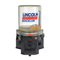
Locating Blockage in Lincoln Quicklub Systems
Description
In a Lincoln Quicklub Lubrication System, free flow of lubricant from the pump through the transmission
system and the bearings is necessary. If any portion of this transmission system (a divider valve, line fitting or
any bearing) does not freely accept and pass its portion of the lubricant a blockage has occurred. This
blockage will cause a higher than normal pumping pressure to be developed by the pump. Depending on the
application or system design, this blockage with its resultant high pump pressure will usually cause a
complete loss of lubricant flow into the total system and no bearing will be receiving lubricant. The loss of flow
due to a blockage is first indicated with the higher than normal system pressure that is developed by the
pump as it attempts to overcome this blockage.
This abnormally higher pressure that is a result of a blockage is limited, isolated, and signalled through the
use of various performance indicators, reset and relief, incorporated into the system design.
Divider Valve
A Quicklub divider valve is a proportioning device consisting of a minimum of three pistons. A primary divider
valve is the first divider valve downstream from the lube pump. A secondary divider valve is any divider valve
receiving lubricant from the primary divider valve.
Outlets
Each outlet on a Quicklub divider valve dispenses .012 in³ per cycle. If an outlet is plugged, the lubricant will
be diverted to the next outlet down allowing proper proportioning of lubricant to all lubrication points.
Warning —Never block lube outlets numbered one and two.
Locating Blockage
If a blockage exists in a Quicklub lubrication system it is caused by one of the following reasons:
(1) Crushed transmission line in the System.
(2) Blocked bearing in the system.
(3) Improperly drilled fitting in the system.
(4) Blocked divider valve in the system.
All servicing and disassembling should be carried out under the cleanest conditions possible. A blockage in a
Quicklub system will be indicated by the fault light and by the pump element relief indicator, exhausting
lubricant to atmosphere. Before proceeding as outlined, make a visual inspection of the system and check for
crushed lines or improper divider valve installation. Verify that each divider valve outlet required to discharge
lubricant can do so and that no plugs have been installed in an outlets one and two of any valve.
Use Filtered Lubricant Only.
Note: Dirt and foreign material are the worst enemies of any lubricating system.
Procedure
1. Use a manual pump with a gauge. Fill the pump with clean, filtered lubricant common to the system.
Connect the manual pump into the inlet of the primary valve and slowly operate pump. If system will not
cycle freely below 1,500 PSI, see Step 2.
2. With pressure on the primary as outlined in step 1, remove one at a time each supply line (if the supply
lines cannot be removed, remove outlet fittings starting from the bottom and working towards the valve
inlet) and attempt to operate manual pump after each line is removed. Do not exceed 2,000 PSI. If
pressure drops and primary cycles freely after a line is removed then blockage is downstream in the area
that is being served from that outlet. See Step 3. If all feed lines are removed and primary will not cycle,
blockage is in this divider valve. Note: When a feed line of a blocked area is removed a small shot of
 Loading...