C
cunninghamjosephJul 27, 2025
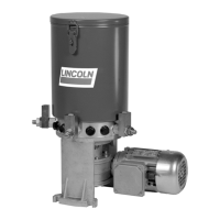
What to do if there is a blockage in the Lincoln Water Pump Quicklub lubrication system?
- SSavannah GonzalezJul 28, 2025
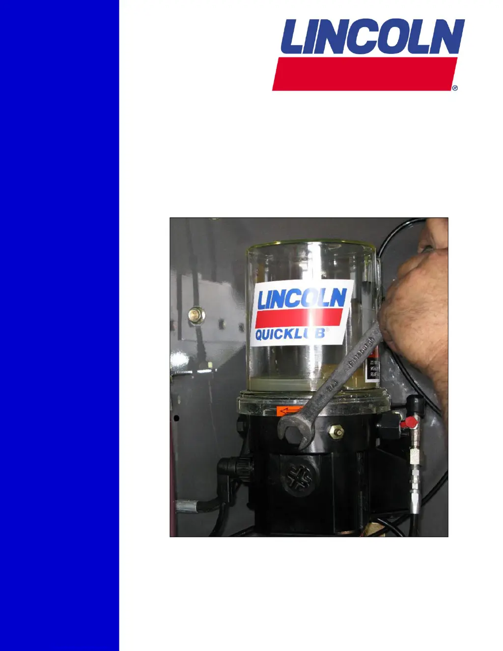
If you encounter a blockage in the Quicklub lubrication system of your Lincoln Water Pump, start with a visual inspection. Check for crushed lines, improperly installed divider valves, tight bearings, and improperly drilled fittings or lube inlet ports. Correct any issues found. If the primary divider valve is blocked based on testing, it should be replaced.