INSTALLATION
WH25
LINDAB SAFE
32/50
Installations remote from the oor
Refer to the section Construction supports characteris-
tics p.17 for further information.
Comply with the minimum distances indicated on section
Minimum distances p.15.
Floor opening
A opening must be provided in the oor as indicated in the
table and in the drawing
Damper positioning
Connect re damper to the galvanized steel duct as indi-
cated in the drawing, with 4 screws Ø4.2x13
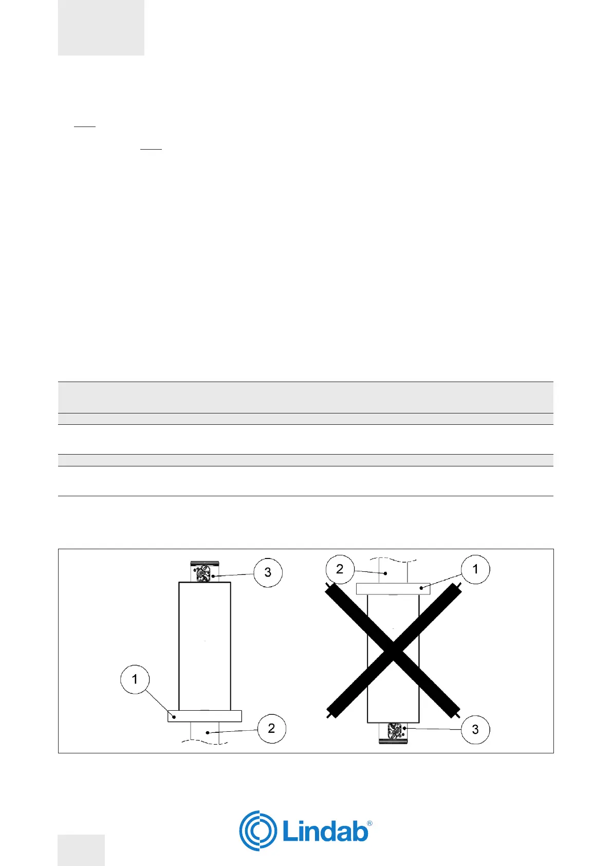
Install the damper with the mechanism facing away from
the oor as indicated in the drawing.
Between re damper and oor the maximum distance is
1000 mm.
The maximum length of the part of duct connected to the
damper is 2150 mm
The re damper has to be xed and suspended from the
ceiling as indicated in the drawing.
The re damper must be positioned just above the oor as
indicated in the drawing.
The hanging structure is composed by:
– 4 Angle connectors 105x105x90 mm
– Screws M8 x 40 mm
– Washers 15 x 9 mm
– Flush anchors M8 x 40 mm
Filling
Fill the space between the oor and the damper using
mortar suitable for use in re resistant constructions, M10
class or higher or plaster putty.
Cover the duct over its entire length and re damper with
2 rock wool panels 50 mm thick and with a density of 140
kg/m³.
Fix rst layer of rock wool panel to the duct with screws Ø5
X 60 mm and washers 40 X 40 mm, and the second one
with screws Ø5 X 120 mm and washers 40 X 40 mm.
Fill the space between rock wool panels and the the
damper with one rock wool panel with minimum thickness
of 50 mm and minimum density of 140 kg/m³.
The panels must be covered externally with endothermic
varnish type PROSTOP E PASTE or HILTI CFS-CT (minimum
thickness of 1 mm) and with an internal perimeter sealant
type PROMOSTOP E PASTE or HILTI CFS-S ACR (minimum
thickness of 1 mm).
Fire resistance classi-
cation
“D” hole size
[mm]
Wall minimum thickness
“S”
[mm]
Sealing
EI 90 S Installation remote from the oor
Floor minimum density 650 kg/m³
EI 90 S
(500 Pa)
From Ø + 25
to Ø + 35
(circular hole)
100 Mortar or plaster putty sealing
EI 120 S Installation remote from the oor
Floor minimum density 650 kg/m³
EI 120 S
(300 Pa)
From Ø + 25
to Ø + 35
(circular hole)
150 Mortar or plaster putty sealing
The re damper must be positioned just above the oor as indicated in the drawing�
1. Floor
2. Duct
3. Fire damper
WH25
LINDAB SAFE
32/50
 Loading...