SPECIFICATION TEXT
WH25
LINDAB SAFE
46/50
SPECIFICATION TEXT
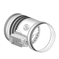
Series WH25 compact circular re dampers
Description
WH25 circular re damper tested for re resistance and
smoke seal with 500 Pa depression as per EN 1366-2, classi-
ed according to EN 13501-3 and CE marked according to
European Regulation UE 305/2011 and EN 15650 standard.
Allows maximum safety for re protection inside buildings
providing perfect heat insulation and cold and hot smokes
tightness. Can be connected to re protection alarm sys-
tem or smokes detection to anticipate blade closure be-
fore re, prevents indirect damages caused by smokes
generated by combustion.
Technical characteristics
• Available diameters from 100 to 315 mm
• Air duct connection gasket.
• Lindab Safe: The system is based on a double, factory-in-
stalled seal made of EPDM rubber. This seal makes the
system quick and easy to mount. Refer to Lindab web
site for further information.
• Closing mechanism built according to UNI 10365, with
thermal fuse certied to ISO 10294-4, a test button to
check the correct working of the damper, a release sys-
tem to block the damper in closed position and a visual
signal "open/closed". The closing mechanism can be eas-
ily interchanged and substituted:
– with mechanical release and manual rearming
– with mechanical release and manual rearming, can be
released remotely via a magnet and electric and signal
– with electric release and rearming, via and integrat-
ed Siemens or Belimo system tested according to EN
15650, composed by an electric thermal fuse and re-
mote controlled servomotor via an electrical signal
• Blade damper made from calcium silicate insulating ma-
terial, rotating on steel gudgeon pins, complete with sil-
icon lip gasket for the air seal of cold smoke, as per EN
1366-2
• Thermal, expanding graphite gasket
• Thermal fuse with melting point certied ISO 10294-4 at
70 °C or 95 °C (version with mechanical release) or at 72
°C (version with servo motor)
• Absence of thermal bridge between the wall of installa-
tion and the ducts before and after
• Resistance to salt spray, tested with severity 2, according
to EN 60068-2-52
• Casing leakage Class C according to EN 1751
Installation
• Installation within vertical rigid walls made from aerated
concrete blocks, standard concrete or masonry with a
minimum thickness of 100 mm and minimum density of
550 kg/m³ (EI 120 S)
Mortar or plaster putty sealing
Plasterboard and rock wool 100 kg/m³ sealing (EI 90 S)
• Installation within light plasterboard walls with mini-
mum thickness of 100 mm and sealed with rock wool
minimum density 80 kg/m³ (EI 60 S) or rock wool mini-
mum density 100 kg/m³ (EI 90 S) or mortar or plaster put-
ty (EI 120 S)
• Installation within light walls made with gypsum blocks
100 mm thick and minimum density 995 kg/m³ (EI 120 S)
or minimum thickness of 70 mm and minimum density
995 kg/m³ (EI 90 S)
• Installation within concrete oors with a minimum thick-
ness of 150 mm and minimum density of 650 kg/m³ (EI
120 S) or aerated concrete with minimum thickness 100
mm (EI 90 S) and minimum density 650 kg/m³
• Installation with Fire Batt (Weichschott) sealing within
vertical rigid walls made from aerated concrete blocks,
standard concrete or masonry with minimum thickness
100 mm and minimum density 550 kg/m³, within light
plasterboard walls with minimum thickness of 100 mm,
within gypsum blocks light walls with with minimum
thickness 100 mm and minimum density 995 kg/m³ (EI
120 S)
• Installation with Fire Batt (Weichschott) sealing within
concrete oors or aerated concrete with minimum thick-
ness 150 mm and minimum density 650 kg/m³ (EI 90 S)
• Remote installation within vertical rigid walls made from
aerated concrete blocks, standard concrete or masonry
with minimum thickness 100 mm and minimum density
550 kg/m³, within light plasterboard walls with minimum
thickness of 100 mm, within gypsum blocks light walls
with with minimum thickness 100 mm and minimum
density 995 kg/m³ (EI 120 S for 300 Pa and EI 90 S for
500 Pa depression).
• Remote installation with Fire Batt (Weichschott) sealing
within vertical rigid walls made from aerated concrete
blocks, standard concrete or masonry with minimum
thickness 100 mm and minimum density 550 kg/m³,
within light plasterboard walls with minimum thickness
of 100 mm, within gypsum blocks light walls with with
minimum thickness 100 mm and minimum density
995 kg/m³ (EI 120 S for 300 Pa depression and EI 90 S for
500 Pa depression)
• Remote installation within concrete oors with a mini-
mum thickness of 150 mm and minimum density of 650
kg/m³ (EI 120 S for 300 Pa) or aerated concrete with min-
imum thickness 100 mm (EI 90 S for 500 Pa) and mini-
mum density 650 kg/m³
• EI 90 S Installation within vertical light wall (Shaft wall)
• Fire resistance characteristics independent from direc-
tion of the source of the re according to EN 1366-2 ar-
ticle 6.2
• Installation possible with damper blade placed horizon-
tally or vertically, with the mechanism placed in left/right
or above/below
Accessories
• Motorised version with 24 V or 230 V servomotor in-
stalled on the damper
• Set of microswitches with three NO/NC position de-
tecting connectors for open and closed damper, as per
standard UNI 10365
• Immission and Interuption magnet 24/48 V DC
WH25
LINDAB SAFE
46/50
 Loading...