05/30/08 Page 2 of 6
LINE 6 CONFIDENTIAL
1. DO NOT WATER WASH THE BOARD: The potentiometers and tact switches are sensitive to
water washing. If wave soldering is preferred, we recommend using a no-clean flux wave soldering
process, rather than a process that requires washing. The fluxing process wave must be controlled so
as not to have flux migrate inside the switch through the top of the housing. Good venting is
required. No-clean flux vapors can enter the switch if adequate venting is not available. The vapors
will condense on the internal contacts and become an insulator when they solidify.
2. “DO NOT INSTALL” COMPONENTS: Do not install the following components: R117 R125
C158 C142 D3-5 D11 D13 H2-3 J11
3. JACKS: All Jacks, including J1, J3-6 (21-00-6616), J2 (21-08-0002), J7-8 (21-12-0035), and J9 (21-
00-0014) must be mounted flush with the PCB and lined up with the silkscreen outline within +/-1
degree of accuracy. ALL jacks are to be mounted on the TOP SIDE of the PCB. See Photo:
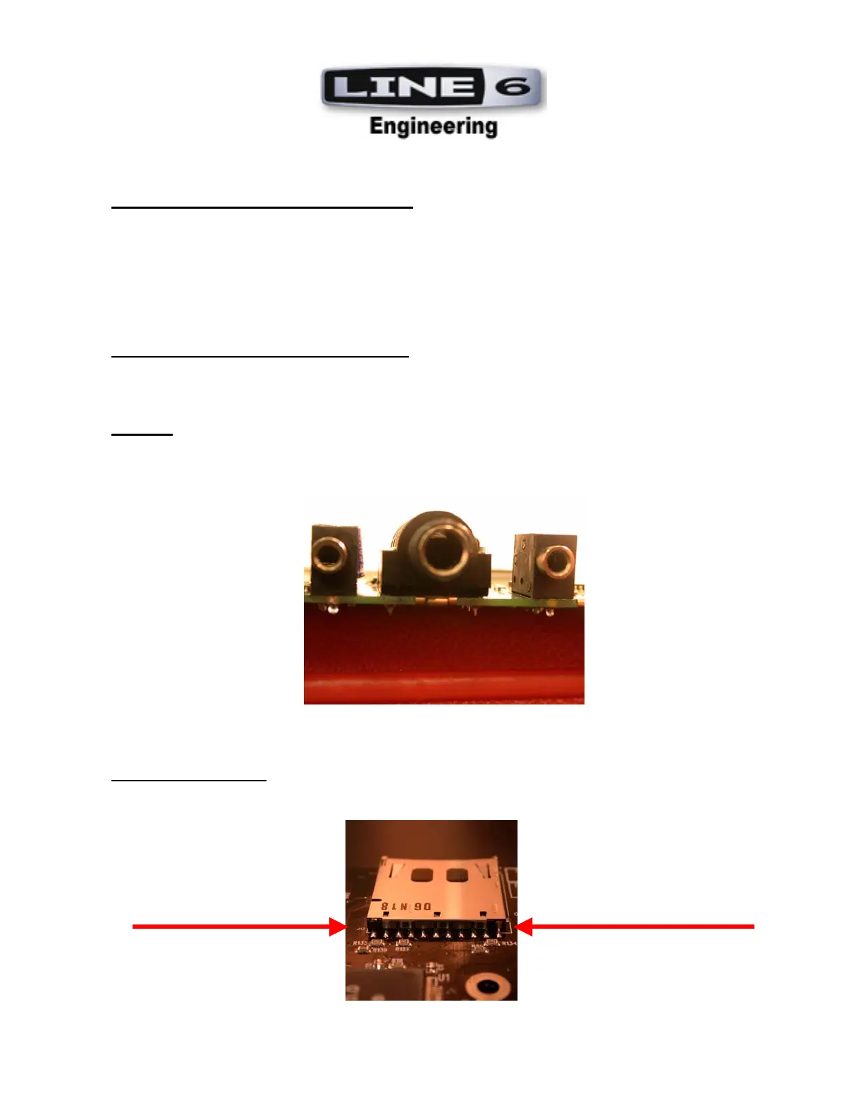
4. SD CARD SOCKET:
J10 (21-18-0900) must be mounted flush with the PCB and lined up with the
silkscreen outline within +/-1 degree of accuracy. The SD Card is mounted on the TOP SIDE of
the PCB. See Photo:
Make sure SD Card is flush before soldering to PCB.
 Loading...